Compound rotorcraft

a rotorcraft and compound technology, applied in the direction of spars/stringers, wheel arrangements, transportation and packaging, etc., to achieve the effect of constant dihedral, constant length, and constant weigh

Active Publication Date: 2017-07-13
AIRBUS HELICOPTERS DEUT GMBH
View PDF0 Cites 34 Cited by
  • Summary
  • Abstract
  • Description
  • Claims
  • Application Information

AI Technical Summary

Benefits of technology

[0031]Advantageously, reduction of the dihedral angle of the lower wing at its root region improves an underlying aerodynamic efficiency of a given wing-fuselage transition. Furthermore, reduction of the sweep angle at the inboard wing section allows keeping its rear main spar away from a predefined propeller burst cone and allows for a clean transition layout from the lower wing's trailing edge to the intermediate compound rotorcraft structure.
[0042]According to one aspect of the present invention, a leading and trailing edge root extension can be integrated within the inboard section of the lower wing. The strake allows for an increase of lift for combat manoeuvring and switches the aerodynamic center of lift further fore. Furthermore, it offers additional volume for equipment housing.

Problems solved by technology

This goes against the classical teachings in the aircraft structure engineering that usually considers as inadequate, providing a connection such as a hinge inside the lower wing between fuselage and each lateral propeller.

Method used


Image

  • Compound rotorcraft
  • Compound rotorcraft
  • Compound rotorcraft

Examples


Embodiment Construction

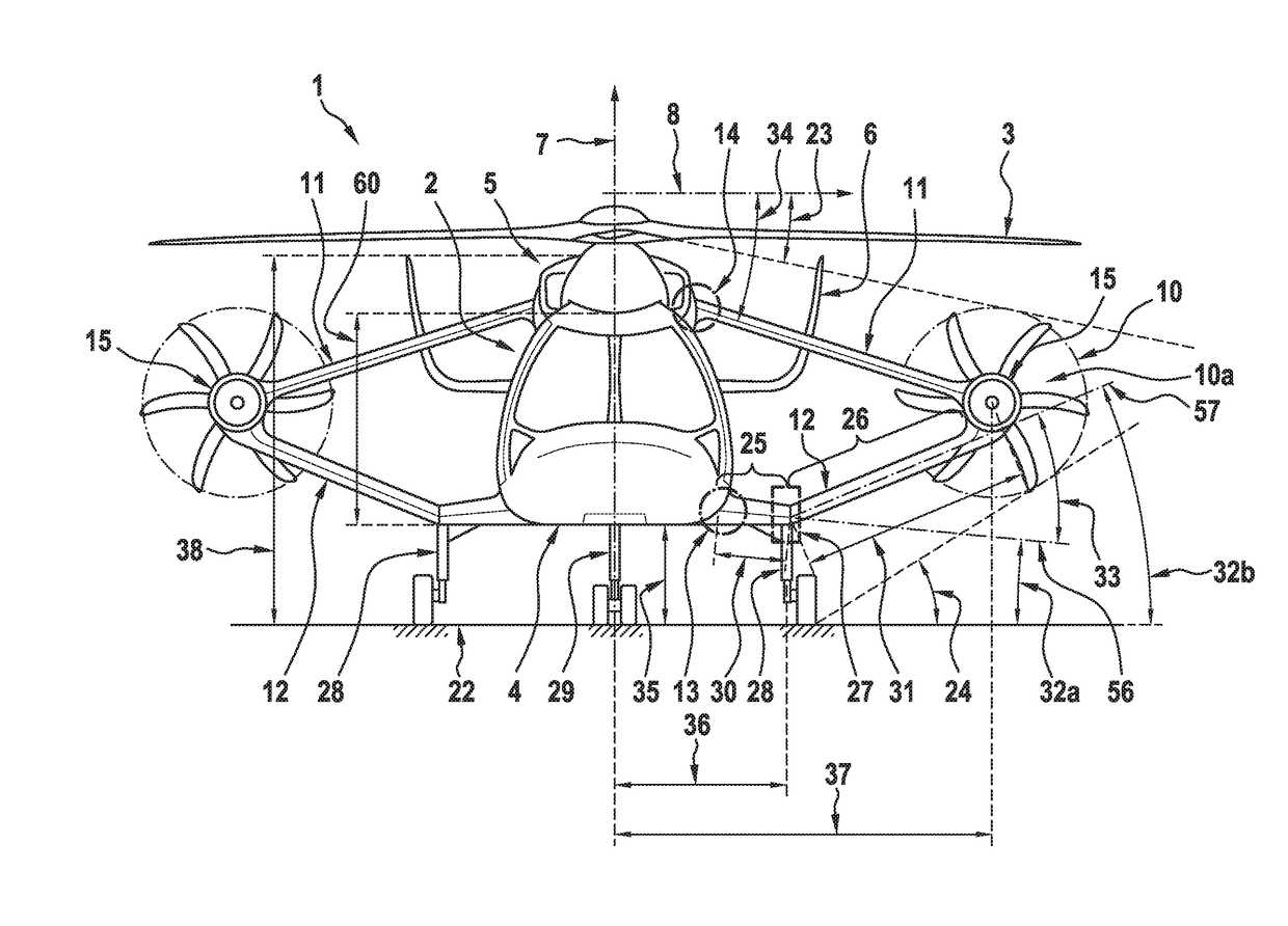
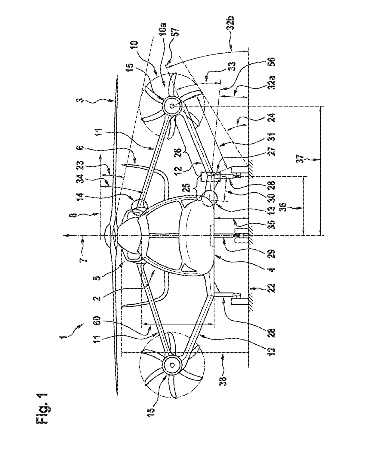
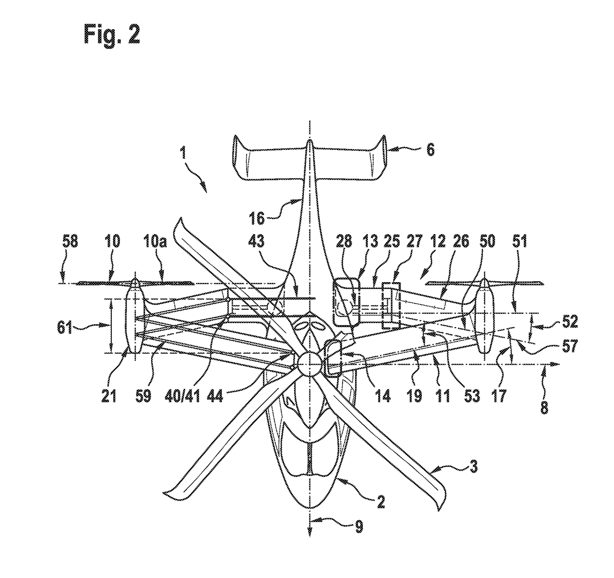
[0066]FIG. 1 shows a compound rotorcraft 1 according to the present invention. The compound rotorcraft 1 illustratively comprises a fuselage 2 with an overall height 38, which exhibits a lower side 4 and an upper side 5 that is opposed to the lower side 4. Furthermore, the compound rotorcraft 1 comprises at least one main rotor 3 that is at least adapted for generating lift in operation. The at least one main rotor 3 is arranged at the upper side 5 of the fuselage 2 and, by way of example, an empennage 6 is rigidly mounted to a tail boom (16 in FIG. 2) defined by the fuselage 2.

[0067]For purposes of illustration, the compound rotorcraft 1 is shown with three mutually orthogonal directions X, Y and Z forming a three-dimensional frame of reference XYZ. A “longitudinal” direction X corresponds to the roll axis (9 in FIG. 2) inherent to the compound rotorcraft 1. Another direction Y, said to be “transverse”, is perpendicular to the roll axis (9 in FIG. 2) and corresponds to the pitch ax...


PUM


Abstract

A compound rotorcraft with a fuselage and at least one main rotor, the fuselage comprising a lower side and an upper side that is opposed to the lower side, the at least one main rotor being arranged at the upper side, wherein at least one propeller is provided and mounted to a fixed wing arrangement that is laterally attached to the fuselage, the fixed wing arrangement comprising at least one upper wing that is arranged at an upper wing root joint area provided at the upper side of the fuselage and at least one lower wing that is arranged at a lower wing root joint area provided at the lower side of the fuselage, the upper and lower wings being at least interconnected at an associated interconnection region.

Description

CROSS REFERENCE TO RELATED APPLICATION[0001]This application claims priority to European patent application No. EP 15400040.0 filed on Sep. 11, 2015, the disclosure of which is incorporated in its entirety by reference herein.BACKGROUND OF THE INVENTION[0002](1) Field of the Invention[0003]The invention is related to a compound rotorcraft with a fuselage, at least one main rotor that is at least adapted for generating lift in operation, and a fixed wing arrangement that is laterally attached to the fuselage, said compound rotorcraft comprising the features of claim 1.[0004](2) Description of Related Art[0005]Compound rotorcrafts and so-called convertiplanes are basically the most relevant concepts aiming to overcome horizontal flight deficiencies of conventional helicopters, i.e. helicopters with a main rotor and an auxiliary tail rotor that is adapted to counter torque, by introducing attributes of fixed-wing aircrafts to such conventional helicopters as compromise. However, a comp...

Claims


Application Information

Patent Timeline
Patent Type & Authority Applications(United States)
IPC IPC(8): B64C27/26B64C27/24B64C3/18B64C27/82B64C3/16B64C25/10B64C1/26B64C27/06B64C25/34
CPCB64C27/26B64C27/06B64C27/24B64C3/185B64C2027/8236B64C3/16B64C25/10B64C1/26B64C27/82B64C25/34B64C27/28B64U10/00B64U30/10B64U30/20B64C39/068B64C2027/8263Y02T50/10B64C27/028B64C2025/325
Inventor FINK, AXELBLACHA, MARTIN
Owner AIRBUS HELICOPTERS DEUT GMBH
Why Eureka
Try Eureka