

A bionic aircraft which realizes the conversion of a flapping rotor and a flapping wing flight mode based on a deformable wing
A technology of bionic aircraft and flight mode, applied in the field of bionic aircraft design
- Summary
- Abstract
- Description
- Claims
- Application Information
AI Technical Summary
Problems solved by technology
Method used
Image

Examples
Embodiment Construction
[0021] The specific implementation manner of the present invention will be described in further detail below in conjunction with the accompanying drawings.
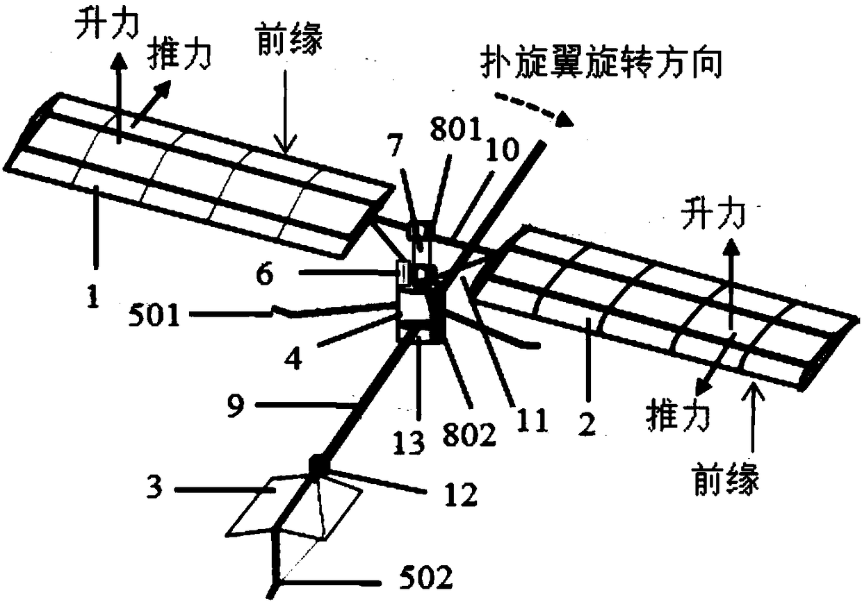
[0022] Such as figure 1 As shown, a bionic aircraft based on the deformed wing to realize the flight mode conversion between the flapping rotor and the flapping wing, including a forward deformed wing 1, a rearward deformed wing 2, an empennage 3, an engine 4, a landing gear 5, a clutch 6, and a drive rod 7 , bearing 8, fuselage 9, deformed wing root connecting rod 10, flapping amplification mechanism rod 11, empennage control system 12, flight control system 13.
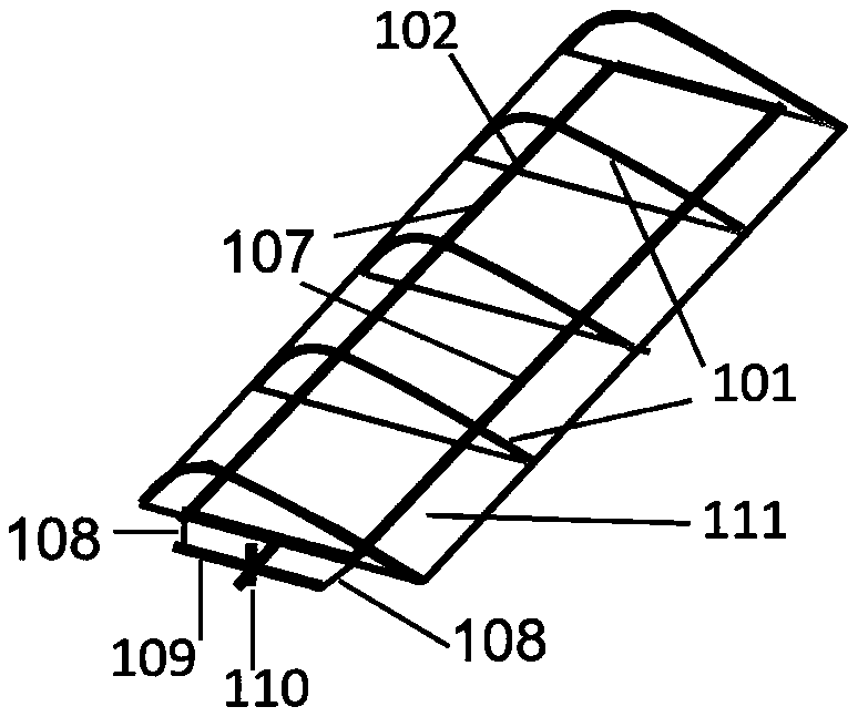
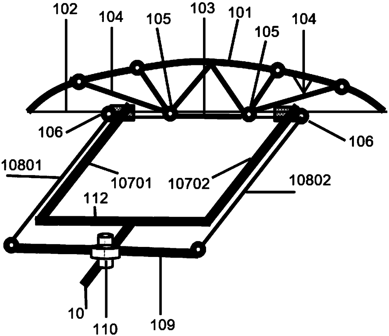
[0023] Such as figure 2 , image 3 As shown, the forward deformed wing 1 includes a bow beam 101, a bow string 102, a bottom bar 103, a support bar 104, a connecting hinge 105, a pulley 106, a beam wing 107, a cable 108, a tie rod 109, and a wing deformation actuator. 110 , skin 111 and spar wing connecting rod 112 ; the spar 107 includes a front spar 10701...
PUM
| Property | Measurement | Unit |
|---|---|---|
| Tensile strength | aaaaa | aaaaa |
| Elastic modulus | aaaaa | aaaaa |
| Tensile strength | aaaaa | aaaaa |
Abstract
Description
Claims
Application Information