Air energy dehumidification device

A technology of air energy and heat pump device, which is applied in air treatment details, control input related to air characteristics, air conditioning system, etc., can solve the problems of single dehumidification method and poor dehumidification effect, and achieve the effect of improving dehumidification efficiency

Active Publication Date: 2015-07-29
CHINA NINGBO AKL ELECTRIC
View PDF5 Cites 2 Cited by
  • Summary
  • Abstract
  • Description
  • Claims
  • Application Information

AI Technical Summary

Problems solved by technology

[0002] At present, ordinary dehumidification devices mainly use the evaporator of the heat pump system to condense hu

Method used


Image

  • Air energy dehumidification device

Examples


Embodiment Construction

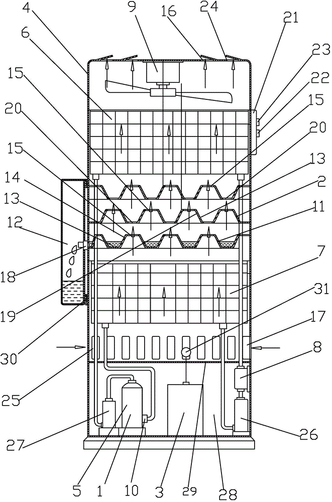
[0008] Below in conjunction with accompanying drawing and specific embodiment the present invention is further described:

[0009] figure 1 The schematic structural diagram of the air energy dehumidification device shown, the air energy dehumidification device includes a heat pump device 1, a water collection device 2, a controller 3 and a casing 4; the heat pump device 1 includes a compressor 5, an evaporator 6, and a radiator 7 , the expansion valve 8 and the fan 9, the refrigerant output joint 10 of the compressor 5 is connected to the radiator 7, the radiator 7 is connected to the expansion valve 8, the expansion valve 8 is connected to the evaporator 6, and the evaporator 6 is connected to the compressor 5; The water collecting device 2 includes a water collecting tank 11 and a water receiving box 12, the water collecting tank 11 communicates with the water receiving tank 12, the water collecting tank 11 is provided with a groove 13 and a boss 14, and the boss 14 is provi...


PUM


Abstract

An air energy dehumidification device comprises a heat pump device, a water collection device, a controller and a shell, wherein the heat pump device comprises a compressor, an evaporator, a radiator, an expansion valve and a fan; a refrigerant output joint of the compressor is connected with the radiator; the radiator is connected with the expansion valve; the expansion valve is connected with the evaporator; the evaporator is connected with the compressor; the water collection device comprises a water collection groove and a water receiving tank; the water collection groove is connected with the water receiving tank; the water collection groove is provided with a groove and a boss; the boss is provided with an air hole; the shell is provided with an air outlet and an air inlet; the controller is connected with the compressor and the fan by a control line; during work, the radiator and the water collection groove are used for carrying out first dehumidification; second dehumidification is carried out by the evaporator; the water collection groove is cooled by condensate water of the evaporator; steam is absorbed by condensate water of the evaporator, and the steam is changed into water to be discharged into the water receiving tank. The dehumidification effect of a dehumidifier is improved.

Description


Claims


Application Information

Patent Timeline
Owner CHINA NINGBO AKL ELECTRIC
Why Eureka
Try Eureka