Composite dehumidifying method based on film and its apparatus and application

A technology of equipment and composite support, which is applied in the field of composite dehumidification, can solve the problems that exhaust heat and humidity cannot be utilized, low dew point dehumidification cannot be realized, and waste heat and humidity cannot be recovered, so as to achieve good economic benefits, adapt measures to local conditions, and realize various effects

Inactive Publication Date: 2005-04-13
SOUTH CHINA UNIV OF TECH
View PDF3 Cites 10 Cited by
  • Summary
  • Abstract
  • Description
  • Claims
  • Application Information

AI Technical Summary

Problems solved by technology

[0003] The current dehumidification methods include compressor refrigeration method, liquid absorption method and rotor adsorption method. These methods consume relatively high energy consumption and cannot recover the waste heat and humidity in the exhaust air.
The Chinese Utility Model Patent No. 00227043.9 discloses a wheel dehumidification technology. The fresh air is directly dehumidified through the dehumidification wheel, and the regeneration fan is connected to the outlet of the regeneration air through the regeneration air duct and the 1 / 4 area of ​​the dehumidification wheel. The regenerative heating The device is connected to the regeneration area of ​​the dehumidification wheel assembly through the regeneration air channel. In this technology, the waste heat and humidity of the exhaust air cannot be utilized, resulting in waste of energy.
The Chinese utility model patent No. 97214969.4 discloses a household circulating liquid hygroscopic agent air dehumidifier, which is mainly provided with a moisture absorption grid vertically arranged by several pieces of superabsorbent fabrics in the moisture absorption chamber, and its lower and upper parts are respectively storage The liquid tank and the moisture absorption spray head are provided with several electric heating elements in the concentration chamber, and the concentration tank and the concentration spray head are respectively arranged on the lower part and the upper part, and the concentration tank and the liquid storage tank are connected by a return pipe. The residual heat and humidity in the indoor exhaust air are not utilized, and the energy consumption of these dehumidification technologies is relatively high
The Chinese utility model patent CN2593094Y announced on December 17, 2003, "air dehumidification and cooling device with heat recovery" can realize the continuous recovery of heat and humidity from exhaust air, but it adopts the method of continuous circulation of hygroscopic solution. Although the system is complicated, But it can't achieve deep dehumidification, the dehumidification capacity is limited, and it can't achieve low dew point dehumidification

Method used


Image

  • Composite dehumidifying method based on film and its apparatus and application
  • Composite dehumidifying method based on film and its apparatus and application
  • Composite dehumidifying method based on film and its apparatus and application

Examples


Embodiment 1

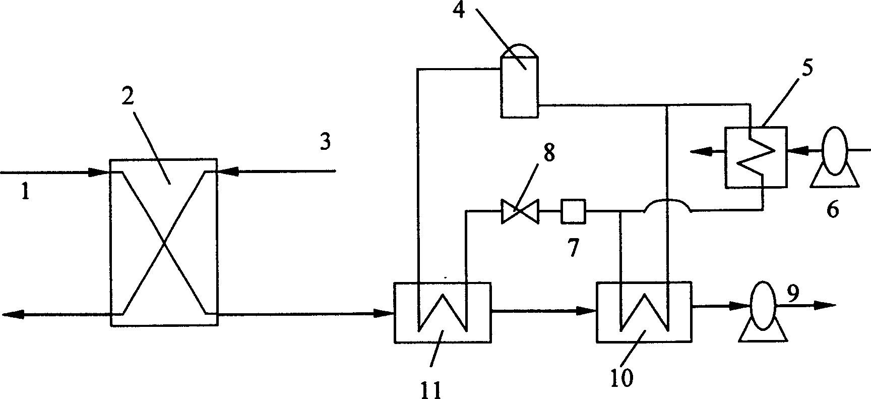
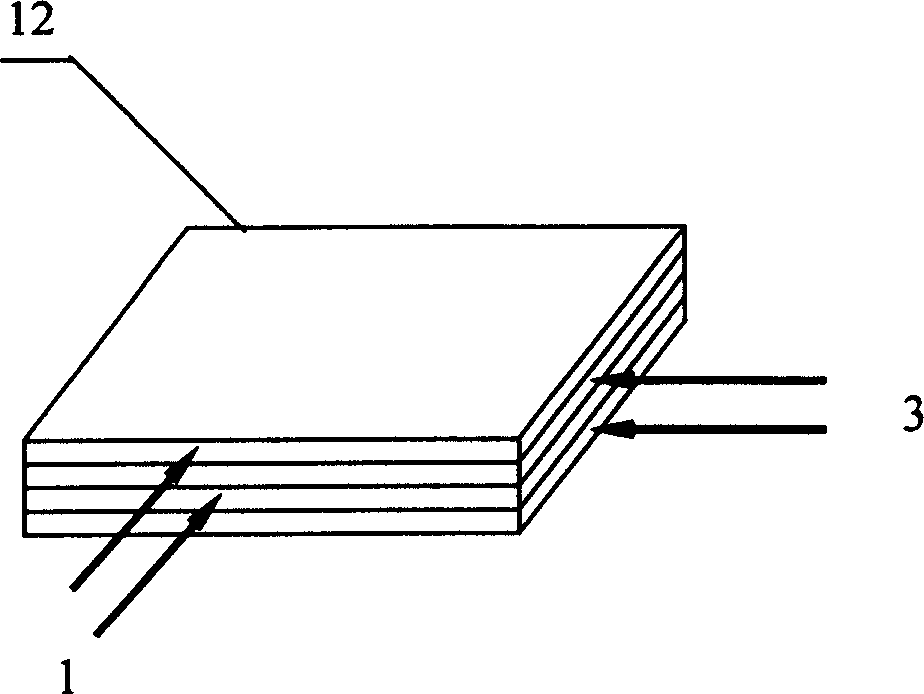
[0024] The specific structure of the present invention is as figure 1 shown by figure 1 It can be seen that this membrane-based composite dehumidification equipment is composed of a membrane exchanger 2 connected with a compression refrigeration dehumidification device, and the structure of the membrane exchanger is as follows: figure 2 As shown, it includes a selective permeable membrane or a composite supporting liquid membrane 12, a fresh air duct 1, and an exhaust duct 3, and a selective permeable membrane or a composite supporting liquid membrane 12 is set between the fresh air duct 1 and the exhaust duct 3; The compression refrigeration dehumidification device includes a compressor 4, condensers 5, 10, fans 6, 9, a liquid receiver 7, an expansion valve 8, and an evaporator 11, and the compressor 4 is connected to two parallel condensers 5, 10 through pipelines. One of the condensers 5 is set opposite to the fan 6, cooled by the outside air driven by the fan 6, and the ...

Embodiment 2

[0028] Another structural form of the present invention is as image 3 shown by image 3 It can be seen that this membrane-based composite dehumidification equipment is composed of a membrane exchanger 2 connected with a liquid absorption dehumidification device, and the structure of the membrane exchanger 2 is the same as in Example 1 (see figure 2 ); the liquid absorption and dehumidification device comprises an absorber 13, an evaporative cooler 14, a cold liquid storage device 15, a water cooler 16, a water storage tank 17, a water pump 18, a solution heat exchanger 19, a regenerator 20, and a thermal liquid storage device 21. Solution pump 22, the absorber 13 is connected to the cold liquid reservoir 15 through a pipeline, the cold liquid reservoir 15 is connected to the solution heat exchanger 19, and the solution heat exchanger 19 is connected to the regenerator 20 at the same time, and the regeneration Heating coil 23 is arranged in device 20; Another group of inlet ...

Embodiment 3

[0032] Another structural form of the present invention is as Figure 4 shown by Figure 4 It can be seen that this membrane-based composite dehumidification equipment is composed of a membrane exchanger 2 connected with a runner dehumidification device, and the structure of the membrane exchanger 2 is the same as in Example 1 (see figure 2 ); said runner dehumidification device comprises dehumidification runner 35 (formed of hygroscopic solids such as lithium chloride, silica gel, calcium chloride), heater 29, heat exchanger 30, regeneration fan 31, motor 33, belt 34, fresh air Fan 36, regeneration air inlet pipe 32, regeneration air outlet pipe 28, drying air outlet pipe 26. Motor 33 is connected with dehumidification runner 35 through belt 34 (also can be provided with gear outside dehumidification runner, motor 33 is connected with dehumidification runner 35 through gear set and carries out transmission), and the regeneration area of ​​described dehumidification runner 3...


PUM


Abstract

The composite dehumidifying process based on membrane includes the following steps: the heat and humidity exchange between fresh air and indoor exhaust via membrane and the deeply dehumidifying in the second stage dehumidifier. The apparatus for said process consists of membrane exchanger and second stage dehumidifier connected together, and the second stage dehumidifier is turning wheel dehumidifier, compression dehumidifier or liquid absorbing dehumidifier. The present invention can recover afterheat and surplus humidity and moves the second stage dehumidifier to low temperature and low humidity area to lower the dew point of exhausted air, and can save power and realize high efficiency and low dew point dehumidifying. The present invention may be used widely.

Description

technical field [0001] The invention relates to composite dehumidification technology, in particular to a membrane-based composite dehumidification method and its equipment and application. Background technique [0002] In recent years, with the development of my country's society and economy, people's living standards have been continuously improved, and higher requirements have been put forward for the comfort of the living environment, among which the demand for dehumidification has become stronger and stronger; in some special departments, such as archives, Tobacco, military industry, medicine, etc., as well as underground or semi-underground buildings, etc., also have higher dehumidification requirements according to different uses. Air conditioning includes the adjustment of temperature and humidity, among which dehumidification is a high energy consumption work, the water vapor content in the air is very small, only a few tens of grams of water ...

Claims


Application Information

Patent Timeline
Patent Type & Authority Applications(China)
IPC IPC(8): B01D53/22F24F3/147
Inventor 张立志
Owner SOUTH CHINA UNIV OF TECH
Why Eureka
Try Eureka