Compact-structure high-voltage power source rapid switching high-voltage switch

A high-voltage switch and fast switching technology, which is applied in high-voltage/high-current switches, electric switches, high-voltage air circuit breakers, etc., can solve the problems of reduced work efficiency, long switching time, and reduced conductivity, so as to ensure reliability and stability High performance, reduced installation space, simplified and compact structure

Inactive Publication Date: 2015-07-29
丁雪强
View PDF6 Cites 0 Cited by
  • Summary
  • Abstract
  • Description
  • Claims
  • Application Information

AI Technical Summary

Problems solved by technology

[0003] Chinese patent application 200610154471.3 discloses an outdoor high-voltage dual-power vacuum circuit breaker. This type of vacuum circuit breaker is equipped with a high-voltage dual-power conversion device consisting of a chained double-throw isolating switch on the vacuum circuit breaker. Although this method realizes high-voltage The automatic switching of dual power supplies is equipped with electrical interlocking and mechanical interlocking, which reduces the possibility of two high-voltage feeds at the same time. It is an ideal high-voltage dual power switching device at present, but there are still drawbacks. In the external environment, with the increase of the number of times and time of use, the surface of the contact will continue to oxidize, resulting in an increase in the resistance of the contact and a decrease in the conductivity, and the contact is prone to heat and burnout.
In addition, the specific switching operation process of this kind of dual-power vacuum circuit breaker is: first disconnect the dynamic and static conductive contacts in the vacuum interrupter, and then use the double-throw isolating switch to switch between dual power sources, so the switching time is long and generally requires More than 10 seconds, such a long power outage time will cause the electrical appliances to restart before they can run, seriously reducing work efficiency

Method used


Image

  • Compact-structure high-voltage power source rapid switching high-voltage switch

Examples


Embodiment 1

[0017] (Embodiment 1, fast switching high-voltage switch)

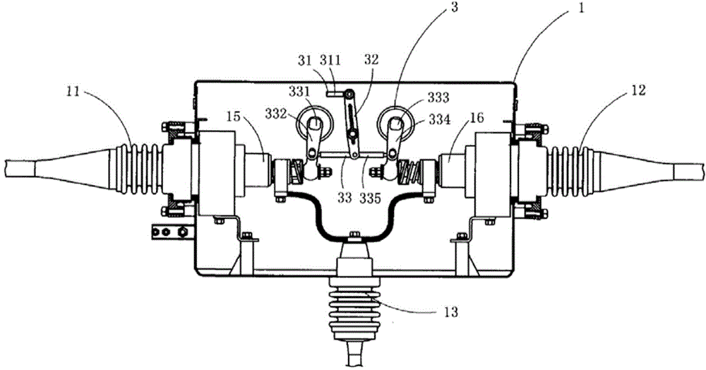
[0018] Fig. 1 is a schematic structural view of the present invention, showing a specific embodiment of the present invention.

[0019] This embodiment is a fast-switching high-voltage switch, as shown in Figure 1, including the main power terminal 1, the auxiliary power terminal 2, the outlet terminal 3, the switching operation mechanism 4, and the main vacuum arc extinguisher electrically connected to the main power terminal 1 Chamber 5, the main trip mechanism 6 for driving the moving contact in the main vacuum interrupter 5, the auxiliary vacuum vacuum interrupter 7 electrically connected to the auxiliary power terminal 2, and the auxiliary vacuum interrupter for driving Auxiliary tripping mechanism 8 in which the middle moving contact moves; the switching operation mechanism 4 includes a driving mechanism 41 having a driving arm 411, a lever 42, and a device for synchronously driving the main tripping...

Embodiment 2

[0023] (Embodiment 2, high-voltage power supply fast switching method)

[0024] This embodiment is the working method of the above-mentioned embodiment 1. As shown in FIG. The main tripping mechanism 6 for head movement, the auxiliary vacuum interrupter for switching on and off the auxiliary power supply, the auxiliary tripping mechanism 8 for driving the movable contact in the auxiliary vacuum interrupter to move, the interlocking mechanism 43, and the driving mechanism 41 ; The main vacuum interrupter 5 and the auxiliary vacuum interrupter are on the same straight line and arranged symmetrically to each other, and the main tripping mechanism 6 and the auxiliary tripping mechanism 8 are also arranged symmetrically to each other; the driving mechanism 41 passes A lever mechanism drives the interlocking mechanism 43 to synchronously drive the main tripping mechanism 6 and the secondary tripping mechanism 8 to perform the tripping action.

[0025] Above-mentioned em...


PUM


Abstract

The invention discloses a high-voltage power supply quick switching method. A main vacuum arc extinguish chamber for switching on / off a main power supply, a main tripping mechanism for driving a moving contact in the main vacuum arc extinguish chamber to move, an auxiliary vacuum arc extinguish chamber for switching on / off an auxiliary power supply, an auxiliary tripping mechanism for driving a moving contact in the auxiliary vacuum arc extinguish chamber to move, an interlocking mechanism and a driving mechanism are arranged in a same shell, wherein the driving mechanism synchronously drives the main tripping mechanism and the auxiliary tripping mechanism to trip through the interlocking mechanism. A quick switching high-voltage switch comprises a main power supply binding post, an auxiliary power supply binding post, an outgoing line post, a switching operation mechanism, the main vacuum arc extinguish chamber electrically connected with the main power supply binding post, the main tripping mechanism for driving the moving contact in the main vacuum arc extinguish chamber to move, the auxiliary vacuum arc extinguish chamber electrically connected with the auxiliary power supply binding post and the auxiliary tripping mechanism for driving the moving contact in the auxiliary vacuum arc extinguish chamber to move. By the invention, switching between double power supplies requires short time and approaches to non-time difference switching.

Description

technical field [0001] The invention belongs to the technical field of high-voltage dual power supply switch structure design, and in particular relates to a high-voltage power supply fast switching method and a fast switching high-voltage switch. Background technique [0002] At present, in order to improve the reliability of power supply, a large number of dual power supply lines (two power supply lines, generally one power system line and one self-contained line) are used in the power supply system. When the power supply of one line fails, the other line supplies power. . For this reason, control devices are needed, and no less than two high-voltage switchgears should be used indoors, and no less than two high-voltage switches on poles should be used outdoors, so as to realize the requirements of selecting power supply lines. This control method not only increases the user's equipment and operating costs, but also poses hidden dangers of power supply accidents. For two ...

Claims


Application Information

Patent Timeline
Patent Type & Authority Applications(China)
IPC IPC(8): H01H33/666
CPCH01H33/52H01H33/66H01H33/666
Inventor 不公告发明人
Owner 丁雪强
Why Eureka
Try Eureka