a resonant circuit

A resonant circuit and resonant technology, which is applied in the direction of electrical components, electric variable adjustment, output power conversion devices, etc., can solve the problems of large voltage stress of the switch tube and high turn-off current of the switch tube, so as to avoid voltage stress and realize soft shutdown. broken effect

Active Publication Date: 2019-03-05
EMERSON NETWORK POWER CO LTD
View PDF5 Cites 0 Cited by
  • Summary
  • Abstract
  • Description
  • Claims
  • Application Information

AI Technical Summary

Problems solved by technology

However, LLC also has its corresponding disadvantages. For example, when it deviates from the resonance point, the ratio of the turn-off current of the switch tube to the peak value of the circuit is relatively high. If it is directly hard-off, it will cause a large voltage stress on the switch tube.

Method used


Image

  • a resonant circuit
  • a resonant circuit
  • a resonant circuit

Examples


Embodiment 1

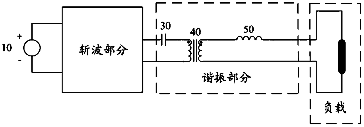
[0026] Such as figure 2 Shown is a schematic diagram of a resonant circuit in an embodiment of the present invention, and the circuit includes:

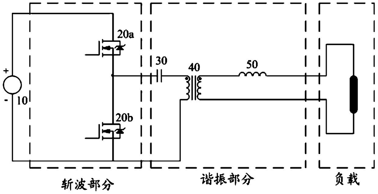
[0027] A chopping part, the input end of the chopping part is connected to both ends of the DC power supply 10, and is used to convert the DC power input by the DC power supply 10 into an AC power output;

[0028] The resonant part includes a capacitor 30, a transformer 40 and an inductance 50; one end of the primary side of the transformer 40 is connected to an output end of the chopping part after the capacitor 30 is connected in series, and the other end of the primary side of the transformer 40 is connected to the chopping part. The other output end: one end of the secondary side of the transformer 40 is connected to one end of the load after being connected in series with the inductor 50 , and the other end of the secondary side of the transformer 40 is connected to the other end of the load.

[0029] Among them, the chopper p...

Embodiment 2

[0082]Embodiments of the present invention also provide a figure 2 The turn-off control method of the switching tube in the resonant circuit shown includes:

[0083] In each resonant cycle of the resonant circuit, the off-time of the switching tube in the chopper part of the resonant circuit is controlled to be within a preset time period; the preset time period is a time period during which the switch tube bears non-forward current.

[0084] By controlling the switch tube to be turned off when receiving a non-forward current, the soft turn-off of the switch tube can be realized.

[0085] Preferably, the preset time period is specifically greater than or equal to T 1 / 2 and less than or equal to T 2 time period; among them, T 1 is the resonant period of the resonant circuit when the load is no-load, T 2 is the resonant period of the resonant circuit when the load is short-circuited, T 2 ≥T 1 / 2.

[0086] Among them, the resonant period T of the resonant circuit when th...


PUM


Abstract

The invention provides a resonance circuit which comprises a chopper portion and a resonance portion. The input end of the chopper portion is connected to the two ends of a DC power supply (10) so as to convert DC power input by the DC power supply (10) into AC power and output the AC power. The resonance portion comprises a capacitor (30), a transformer (40) and an inductor (50), wherein one end of the primary side of the transformer (40) is connected with the capacitor (30) in series and then connected to one output end of the chopper portion, the other end of the primary side of the transformer (40) is connected to the other output end of the chopper portion, one end of a secondary side of the transformer (40) is connected with the inductor (50) in series and then connected to one end of a load, and the other end of the secondary side of the transformer (40) is connected to the other end of the load. The resonance circuit in the embodiment of the invention realizes soft switching off of a switch tube in the chopper portion.

Description

technical field [0001] The invention relates to the field of circuit design, in particular to a resonant circuit. Background technique [0002] LLC has become a popular topology in the current power electronics industry. It has the characteristics of soft recovery of the diode on the rectifier side, soft turn-on of the primary side switch, and low current turn-off. It has become the first choice for high-efficiency applications. However, LLC also has its corresponding disadvantages. For example, when it deviates from the resonance point, the ratio of the turn-off current of the switch tube to the peak value of the circuit is high. If it is directly turned off hard, it will cause a large voltage stress on the switch tube. Contents of the invention [0003] The embodiment of the present invention provides a resonant circuit, which is used to realize the soft turn-off of the switching tube in the resonant circuit. [0004] An embodiment of the present invention provides a re...

Claims


Application Information

Patent Timeline
Patent Type & Authority Patents(China)
IPC IPC(8): H02M3/335
Inventor 倪同
Owner EMERSON NETWORK POWER CO LTD
Why Eureka
Try Eureka