speaker module

A speaker module and module technology, which is applied in the direction of speaker transducer fixing, sensor, transducer diaphragm, etc., can solve the problem of reducing the acoustic performance of the speaker module, increasing the F0 of the speaker module, and occupying the space of the rear acoustic cavity, etc. problems, to achieve the effect of increasing work stability and service life, reducing F0, and broadening the frequency band

Active Publication Date: 2018-09-07
GOERTEK INC
View PDF5 Cites 0 Cited by
  • Summary
  • Abstract
  • Description
  • Claims
  • Application Information

AI Technical Summary

Problems solved by technology

When the volume of the rear acoustic cavity of the speaker module is constantly decreasing, choosing a diaphragm with greater compliance is an effective way to reduce F0. However, the diaphragm with greater compliance is easy to curl and difficult to assemble. The assembly of a large diaphragm is difficult, and the technician will paste a ring-shaped metal ring on the edge of the diaphragm as a support to prevent the diaphragm from curling
Although the annular support effectively prevents the diaphragm from curling and reduces the difficulty of assembly, it will occupy a part of the space of the rear acoustic cavity, resulting in a decrease in the effective volume of the rear acoustic cavity, which leads to an increase in the F0 of the speaker module, and Reduced acoustic performance of the speaker module

Method used


Image

  • speaker module
  • speaker module
  • speaker module

Examples


Embodiment 1

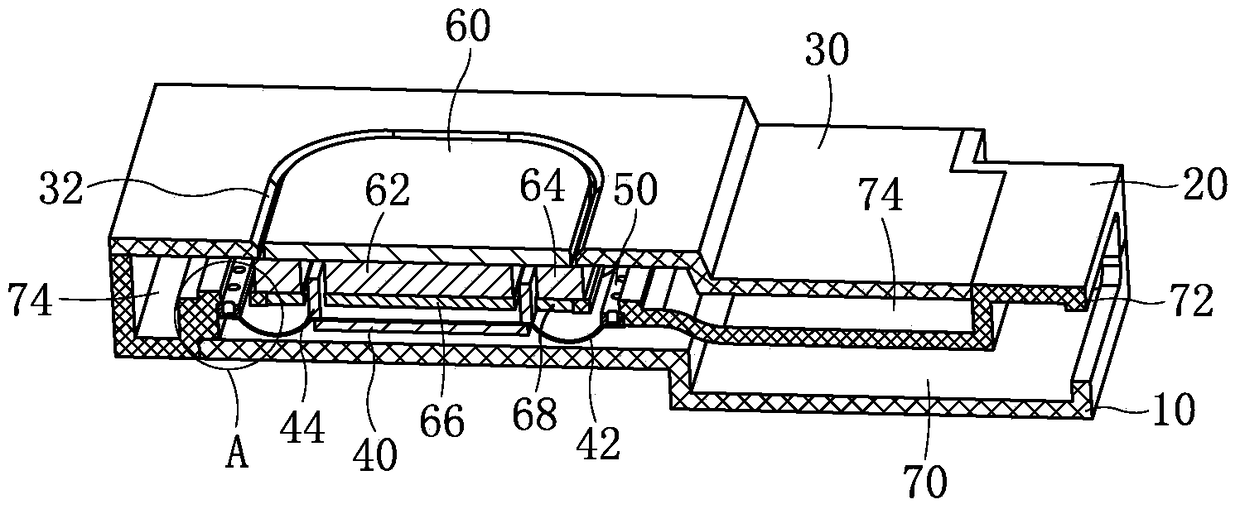
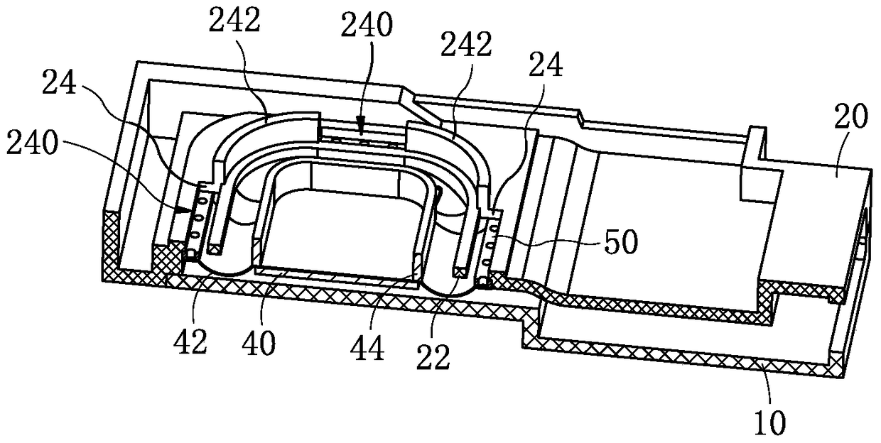
[0032] Such as figure 1 As shown, a loudspeaker module includes a shell, and the shell is composed of an upper shell 10, a middle shell 20, and a lower shell 30 that are sequentially combined, and the space surrounded by the upper shell 10, the middle shell 20, and the lower shell 30 contains Vibration system and magnetic circuit system. The vibration system divides the entire module inner cavity into two cavities, the front acoustic cavity 70 and the rear acoustic cavity 74. The vibration system forms the front acoustic cavity 70 together with the upper shell 10 and the middle shell 20; Together they form a rear acoustic cavity 74. The module is a side sound module, and the sound hole 72 is set at the end of the module away from the vibration system and the magnetic circuit system, and is jointly surrounded by the upper shell 10 and the middle shell 20 .

[0033] Such as figure 1 As shown, the vibration system includes a diaphragm 42 whose edge is fixed on the middle shell...

Embodiment 2

[0041] This embodiment is basically the same as Embodiment 1, the difference is that:

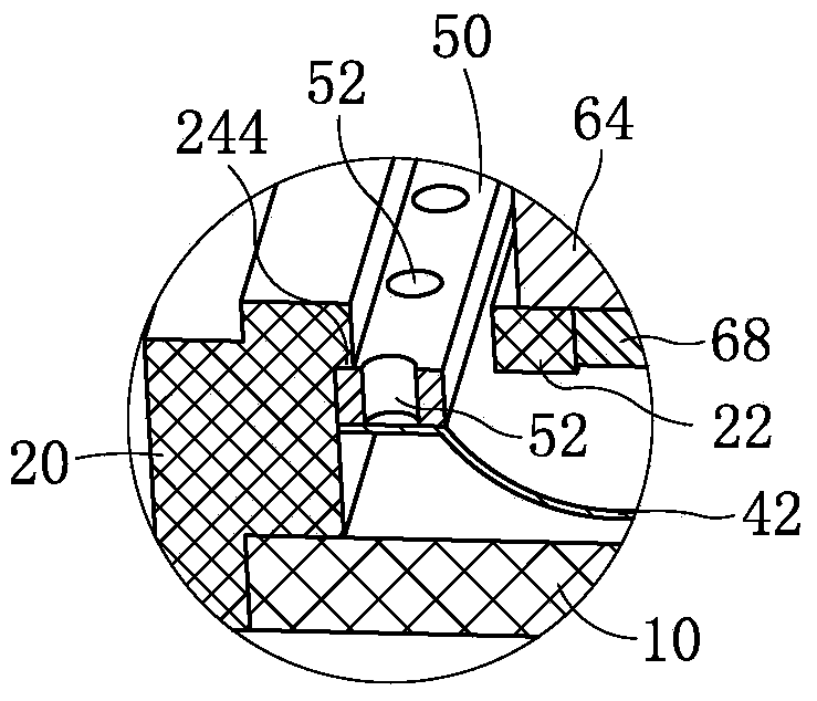
[0042] Such as Figure 5 As shown together, the enlarged cavity portion 52 is disposed on both side edges of the support member 50 , and in practical applications, the enlarged cavity portion 52 may also be disposed only on one side edge portion of the support member 50 .

[0043] The cavity expansion part 52 is arranged on the edge of the support member 50 and can also play the function of expanding the rear acoustic cavity, but compared with the first embodiment, the bonding strength between the support member 50 and the middle shell and the diaphragm of this embodiment is weaker. Therefore, Embodiment 1 is a preferred solution of the present invention.

[0044] The present invention reduces the volume of the support while ensuring the strength of the support by opening holes on the support, increases the effective volume of the rear acoustic cavity, effectively reduces the F0 of the mod...


PUM


Abstract

Disclosed is a loudspeaker module, comprising a shell, wherein a vibrating system and a magnetic circuit system are accommodated in the shell, the vibrating system comprises a vibrating diaphragm and a voice coil which are combined together; a whole inner cavity of the module is divided by the vibrating diaphragm into two cavities, i.e. a front voice cavity and a rear voice cavity; an edge portion of the vibrating diaphragm is fixed on the shell by using an annular supporting member, a plurality of cavity expansion portions formed by incomplete filling are distributed on the supporting member at intervals, and each of the cavity expansion portions is communicated with the rear voice cavity. The loudspeaker module of the present disclosure solves the technical problem of F0 rising due to the narrow rear voice cavity of the loudspeaker module in the prior art.

Description

technical field [0001] The invention relates to the technical field of electroacoustic products, in particular to a loudspeaker module. Background technique [0002] The loudspeaker module is an important acoustic component of portable electronic equipment, which is used to complete the conversion between electrical signals and sound signals, and is an energy conversion device. Existing loudspeaker modules usually include a shell, which accommodates a vibration system and a magnetic circuit system. The vibration system includes a combined diaphragm and voice coil. The diaphragm separates the entire module cavity into two front and rear sound chambers. cavity. F0 (resonance frequency) is an important indicator of the speaker module, the lower its value, the wider the frequency band of the speaker module and the better the acoustic performance. FO is mainly affected by the volume of the rear acoustic cavity of the module and the compliance of the diaphragm. The larger the vo...

Claims


Application Information

Patent Timeline
Patent Type & Authority Patents(China)
IPC IPC(8): H04R1/20
CPCH04R1/2842H04R1/025H04R1/2803H04R1/2811H04R1/2857H04R7/127H04R9/025H04R9/06H04R31/006H04R2499/11
Inventor 韩丹杨赟霍新祥刘旭东
Owner GOERTEK INC
Why Eureka
Try Eureka