D2D communication synchronization channel transmission method, D2D communication synchronization channel transmission system, sender and receiver

A technology for synchronizing channels and transmission methods, applied in the field of wireless communication

Active Publication Date: 2015-07-29
ZTE CORP
View PDF4 Cites 13 Cited by
  • Summary
  • Abstract
  • Description
  • Claims
  • Application Information

AI Technical Summary

Problems solved by technology

[0009] The technical problem to be solved by the present invention is to provide a transmission method and system, a sending end and a receiving end of a D2D communication synchroniz

Method used


Image

  • D2D communication synchronization channel transmission method, D2D communication synchronization channel transmission system, sender and receiver
  • D2D communication synchronization channel transmission method, D2D communication synchronization channel transmission system, sender and receiver
  • D2D communication synchronization channel transmission method, D2D communication synchronization channel transmission system, sender and receiver

Examples


Embodiment

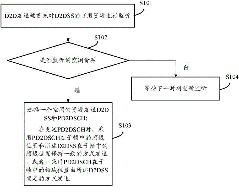
[0085] This embodiment provides a device-to-device communication synchronization channel transmission method, which is applied to the D2D sending end, including:

[0086] The D2D sender sends D2DSS and PD2DSCH, wherein, when sending the PD2DSCH, the frequency domain position of the PD2DSCH in the subframe is consistent with the frequency domain position of the D2DSS in the subframe, or the PD2DSCH is in the subframe The frequency domain position in is determined by the D2DSS.

[0087] Wherein, the D2DSS includes: D2D primary synchronization signal (Primary D2D Synchronization Signal, referred to as PD2DSS) and / or D2D secondary synchronization signal (Secondary D2D Synchronization Signal, referred to as SD2DSS); wherein, both PD2DSS and SD2DSS are sent in the form of a sequence, and PD2DSS The sequence type of SD2DSS is M, and M is a positive integer less than or equal to 3; the sequence type of SD2DSS is N, and N is a positive integer greater than or equal to the total number ...

application example 2

[0174] Application example 2 (the frequency domain position of PD2DSCH is determined by D2DSS)

[0175] In this solution, the number of PD2DSCH and D2DSS included in each subframe may not be in one-to-one correspondence, that is, one D2DSS may be associated with multiple PD2DSCHs. Such as Figure 8 As shown, in the entire D2D transmission bandwidth, there is a group of available resources for synchronization signals, and the synchronization signals correspond to 4 PD2DSCHs. Among them, the determination method of the location of the PD2DSS frequency domain is: PD2DSS carries 3 different sequences, and these 3 sequences correspond to a value in 0, 1, 2, and this value is bound to the number of RBs occupied by PD2DSCH Certainly. For example, 0 indicates that PD2DSCH occupies 2 RBs; 1 indicates that PD2DSCH occupies 4 RBs; 2 indicates that PD2DSCH occupies 6 RBs. The SD2DSS carries 168 different sequences, and these 168 sequences specifically correspond to a value from 0 to 16...

application example 3

[0189] Application Example 3 (The frequency domain position of PD2DSCH is determined by D2DSS)

[0190] Such as Figure 10 As shown, there are 3 groups of D2DSS available resources, and each group of D2DSS available resources corresponds to 1 or more PD2DSCHs, and the specific indication method is the same as that described in Application Example 2.

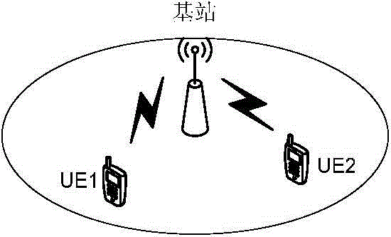
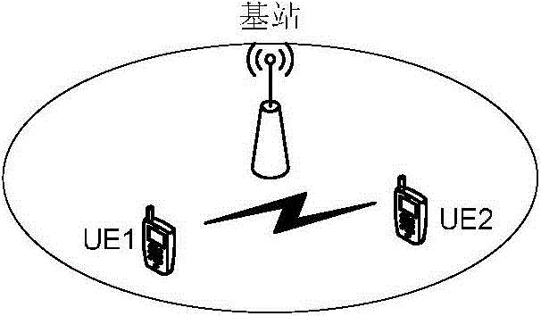
[0191] It can be seen from the above embodiments that, compared with the prior art, the transmission method and system, the sending end and the receiving end of the D2D communication synchronization channel provided in the above embodiments mainly solve the problem of communication between devices in various out-of-coverage scenarios. synchronization issues.


PUM


Abstract

A synchronization channel transmission method and system for D2D communication, a transmit end and a receive end. The system comprises: a transmit end and a receive end. The transmit end comprises a generation module and a transmit module and is used for transmitting a D2DSS and a PD2DSCH. The receive end comprising a receive module and a processing module and is used for receiving the D2DSS and the PD2DSCH. When the PD2DSCH is transmitted, a frequency-domain position of the PD2DSCH in a sub-frame is consistent with a frequency-domain position of the D2DSS in the sub-frame, or the frequency-domain position of the PD2DSCH in the sub-frame is determined by the D2DSS. When the PD2DSCH is received, the PD2DSCH is received at a frequency-domain position the same as a frequency-domain position of the D2DSS, or the PD2DSCH is received at a frequency-domain position determined by the D2DSS.

Description

technical field [0001] The present invention relates to the field of wireless communication, in particular to a device-to-device (Device-to-Device, D2D for short) communication synchronization channel transmission method and system, a sending end and a receiving end. Background technique [0002] Because the cellular communication system realizes the multiplexing of limited spectrum resources, the wireless communication technology has been developed vigorously. In a cellular system, when there is a service to be transmitted between two user equipments (UE1), the service data from user equipment 1 (UE1) to user equipment 2 (UE2) will first be transmitted to the base station through the air interface 1. Base station 1 transmits the user data to base station 2 through the core network, and base station 2 then transmits the above service data to UE2 through the air interface. The service data transmission from UE2 to UE1 adopts a similar processing flow. Such as figure 1 As s...

Claims


Application Information

Patent Timeline
IPC IPC(8): H04W56/00
CPCH04W56/001H04W56/002
Inventor 袁明夏树强吴栓栓袁弋非杨瑾
Owner ZTE CORP
Why Eureka
Try Eureka