SCR electronic switch for achieving synchronization of drive signals

A technology for electronic switches and driving signals, applied in electronic switches, electrical components, pulse technology, etc., can solve the problems of incompatibility, infeasible optical fiber transmission, and high synchronization requirements of SCR driving signals, so as to solve the synchronization problem and improve the Effects along properties

Inactive Publication Date: 2016-08-24
苏州泰思特电子科技有限公司
View PDF4 Cites 16 Cited by
  • Summary
  • Abstract
  • Description
  • Claims
  • Application Information

AI Technical Summary

Problems solved by technology

However, this approach is not suitable for fast rising edge applications such as pulsed power
Under this working condition, the du / dt level of the SCR device is very high, so the synchronization of the SCR driving signal is very high, and optical fiber transmission is not feasible

Method used


Image

  • SCR electronic switch for achieving synchronization of drive signals
  • SCR electronic switch for achieving synchronization of drive signals

Examples


Embodiment 1

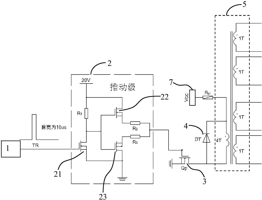
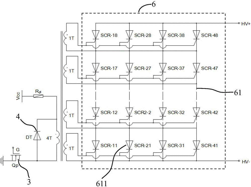
[0018] Embodiment 1: An SCR electronic switch that realizes drive signal synchronization, as shown in the accompanying drawings, includes: a square wave generator 1, a push-pull circuit 2, an amplifying MOS transistor 3, a freewheeling diode 4, a coupling transformer 5 and a controllable Silicon array 6, the square wave generator 1 is connected to the input end of the push-pull circuit 2, the gate of the amplifying MOS transistor 3 is connected to the output end of the push-pull circuit 2, the primary side of the coupling transformer 4 and the secondary side Each side has a primary coil and at least 2 secondary coils, and the source and drain of the amplifier MOS transistor 3 are located between the ground and the primary coil of the coupling transformer 4;

[0019] The push-pull circuit 2 includes a first power MOS tube 21, a second power MOS tube 22 and a third power MOS tube 23, the second power MOS tube 22 is connected in parallel with the third power MOS tube 23, and the f...

Embodiment 2

[0023] Embodiment 2: A kind of SCR electronic switch that realizes drive signal synchronization, including: square wave generator 1, push-pull circuit 2, amplifying MOS transistor 3, freewheeling diode 4, coupling transformer 5 and thyristor array 6, described The square wave generator 1 is connected to the input end of the push-pull circuit 2, the gate of the amplifying MOS transistor 3 is connected to the output end of the push-pull circuit 2, and the primary side and the secondary side of the coupling transformer 4 respectively have a primary coil and at least two secondary coils, the source and drain of the amplifying MOS transistor 3 are located between the ground and the primary coil of the coupling transformer 4;

[0024] The push-pull circuit 2 includes a first power MOS tube 21, a second power MOS tube 22 and a third power MOS tube 23, the second power MOS tube 22 is connected in parallel with the third power MOS tube 23, and the first power MOS tube 21 and the third p...


PUM


Abstract

The invention discloses an SCR electronic switch for achieving synchronization of drive signals, and the electronic switch comprises a square-wave generator, a push-pull circuit, an amplification MOS tube, a fly-wheel diode, a coupling transformer, and a silicon controlled rectifier array. The square-wave generator is connected with the input end of the push-pull circuit, and the grid electrode of the amplification MOS tube is connected to the output end of the push-pull circuit. The primary side and secondary side of the coupling transformer are respectively provided with at least one primary coil and at least two secondary coils. The fly-wheel diode is in parallel connection with the primary coil of the coupling transformer, and the positive electrode of the fly-wheel diode and one end of the primary coil are respectively connected to a drain electrode of the amplification MOS tube. The negative electrode of the fly-wheel diode and the other end of the primary coil are respectively connected to one high-voltage power supply. The silicon controlled rectifier array is formed by the parallel connection of at least two silicon controlled rectifier branch circuits, wherein each silicon controlled rectifier branch circuit is formed by the series connection of at least two silicon controlled rectifiers. A high-level output end of each secondary coil of the coupling transformer is connected with the grid electrode of the corresponding silicon controlled rectifier in each silicon controlled rectifier branch circuit. The electronic switch guarantees the high synchronism of drive signals, and solves a problem of the synchronization of drive signals.

Description

technical field [0001] The invention belongs to the technical field of application of power electronic devices, and in particular relates to an SCR electronic switch for synchronizing driving signals. Background technique [0002] SCR is a semi-controlled power device, its turn-on time can be controlled arbitrarily, but the turn-off time can only be determined by the external circuit conditions. The conduction process of the SCR device is actually the process of establishing positive feedback. In order to ensure that the SCR is fully turned on, it is necessary to ensure that the trigger pulse width is much longer than the positive feedback establishment time. [0003] In the power industry, the SCR trigger signal is transmitted through optical fiber. This method can not only meet the high potential isolation requirements, but also improve the anti-interference level of the system, and has been widely used. However, this method is not suitable for fast rising edge applicat...

Claims


Application Information

Patent Timeline
Patent Type & Authority Applications(China)
IPC IPC(8): H03K17/723
CPCH03K17/723
Inventor 陈鹏于辉黄学军
Owner 苏州泰思特电子科技有限公司
Why Eureka
Try Eureka