Adjustable Width Cutting Instrument for Transapical Aortic Valve Resection

An aortic and transapical technology, applied in the direction of surgical cutting instruments, endoscopic cutting instruments, anatomical instruments, etc., can solve the problems of the aortic valve not having the best fit, thrombus, inaccuracy, etc.

An aortic and transapical technology, applied in the direction of surgical cutting instruments, endoscopic cutting instruments, anatomical instruments, etc., can solve the problems of the aortic valve not having the best fit, thrombus, inaccuracy, etc.

CN104812318BActive Publication Date: 2017-11-24AESCULAP AG

Image

  • Adjustable Width Cutting Instrument for Transapical Aortic Valve Resection
  • Adjustable Width Cutting Instrument for Transapical Aortic Valve Resection
  • Adjustable Width Cutting Instrument for Transapical Aortic Valve Resection

Examples


Embodiment Construction

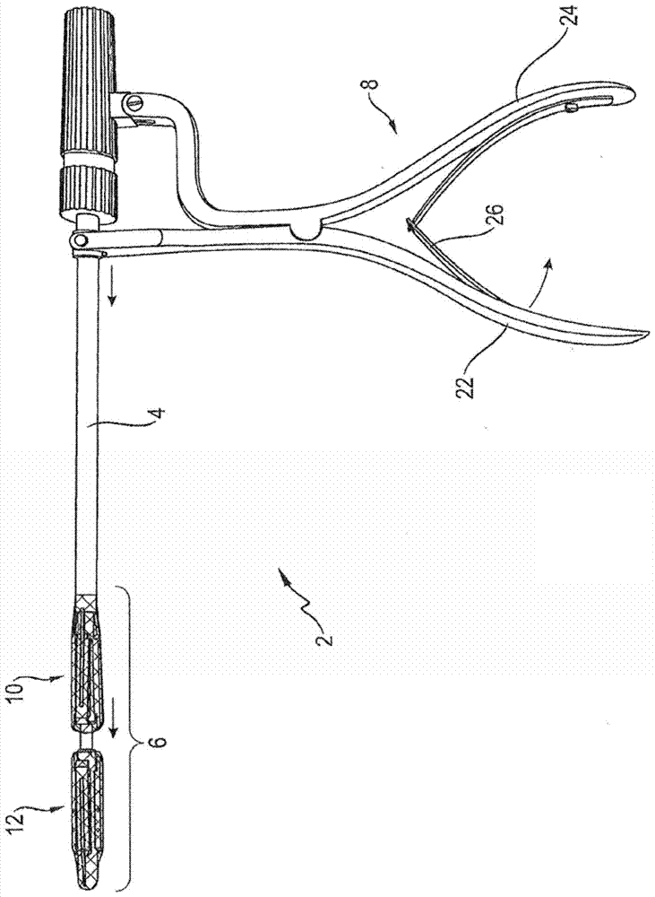
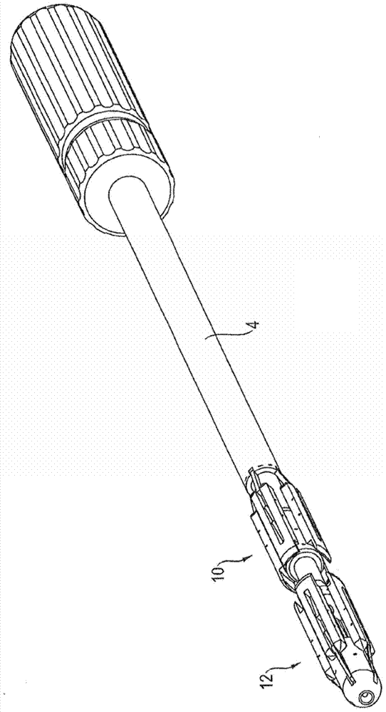
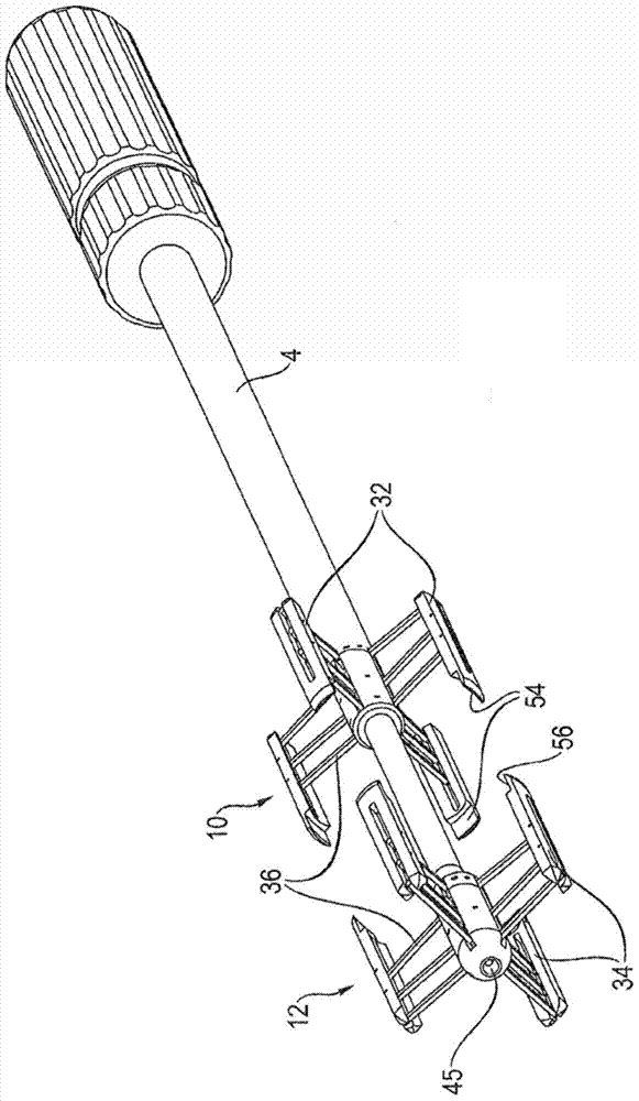
[0074] figure 1 A cutting instrument 2 is shown which is designed according to the invention and which has its distal end of the tool shaft 4 equipped with a cutting unit 6 which can be driven by means of a handpiece 8 arranged on the proximal end of the tool shaft 4 . The shaft 4 may be rigid or flexible; it may be possible to manipulate the shaft by means of a hand piece 8 if necessary. The cutting unit 6 is basically formed as a punch-die unit and consists of two cutting tools 10 and 12 which are arranged axially on the tool shaft 4 and which are movable towards and away from each other by means of a handpiece 8 . More precisely, the proximal cutting tool 10 in the illustrated example acts as a movable punch unit and the distal cutting tool 12 acts as a static die unit. Of course, in alternative designs, the distal cutting tool 12 can be moved towards the proximal cutting tool 10, or both cutting tools can be moved relative to each other.

[0075] The cutting tools 10, 12...


PUM


Abstract

The invention relates to a surgical cutting instrument (2) for transapical aortic valve resection, said instrument having a cutting unit (6) arranged at the distal end of the tool shaft (4) and having a At least one mechanical cutting element (16) for performing circular cutting. According to the invention, at least one cutting element ( 16 ) can be adjusted in a continuously variable manner to different aortic diameters by means of a radially displaceable adjustment mechanism.

Description

technical field [0001] The invention relates to a surgical (in particular endoscopic) cutting instrument for transapical aortic valve resection according to the preamble of claim 1 . Background technique [0002] In the case of aortic valve stenosis or insufficiency, surgery is indicated in many cases where the body's own aortic valve is replaced with an artificial aortic valve. In addition to open surgery (which is performed under general anesthesia using a cardiopulmonary device and uses a saw blade to open the sternum to expose the heart and which must be stopped), minimally invasive surgery can be performed on a beating heart. Aortic valve replacement. In this case, a transfemoral (transfemoral) or transapical (transapical) access route is chosen. [0003] One possible approach is the introduction of an aortic valve prosthesis, which expands automatically or with the aid of a balloon and replaces the body's own aortic valve. However, if the natural aortic valve is not...

Claims


Application Information

Patent Timeline
24 Nov 2017
Publication
CN104812318B
IPC
A61B17/32; A61B17/3205; A61B17/3207; A61B17/00; A61B17/22
CPC
A61B17/320016; A61B17/32053; A61B2017/320716; A61B2017/22097; A61B17/3209
Inventors
佩德罗·莫拉莱斯; 迪特尔·魏斯豪普特