A ring-dipole combination antenna

A combined antenna and vibrator technology, applied in the direction of antenna grounding switch structure connection, radiation element structure, etc., can solve the problems of large area, working frequency band gain and beam instability, etc., and achieve good directional radiation and small cross-polarization characteristics Effect

Active Publication Date: 2017-05-10
江苏众成通信技术有限公司
View PDF4 Cites 0 Cited by
  • Summary
  • Abstract
  • Description
  • Claims
  • Application Information

AI Technical Summary

Problems solved by technology

[0003] Traditional directional antennas need to add a reflective back cavity or a reflector plate. The added reflector should be a quarter wavelength away from the antenna, and the gain and beam instability in the working frequency band can be obtained; electric vibrators and magnons can also be used Coupled structural form to achieve directional radiation characteristics, but this method also requires a larger reflector

Method used


Image

  • A ring-dipole combination antenna
  • A ring-dipole combination antenna
  • A ring-dipole combination antenna

Examples


Embodiment Construction

[0031] Below in conjunction with accompanying drawing, technical scheme of the present invention is described in further detail:

[0032] Examples of the embodiments are shown in the drawings, wherein like or similar reference numerals designate like or similar elements or elements having the same or similar functions throughout. The embodiments described below by referring to the figures are exemplary only for explaining the present invention and should not be construed as limiting the present invention.

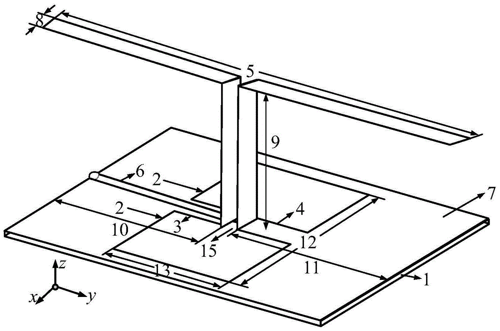
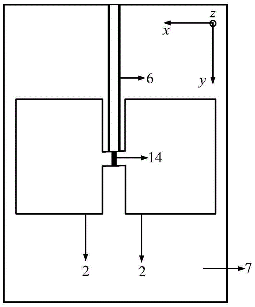
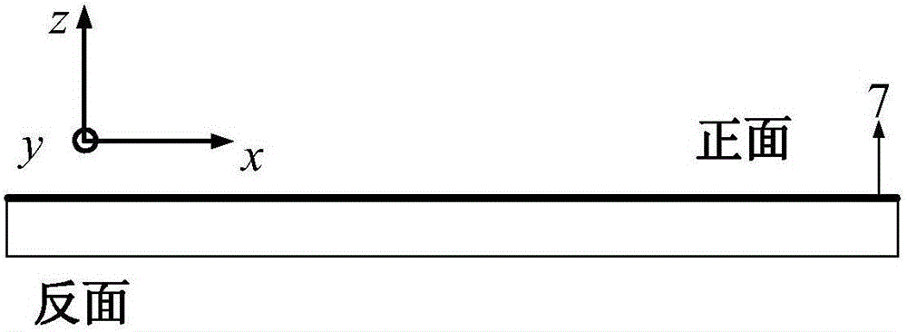
[0033] like Figure 1-Figure 3 As shown, the structure of the present invention is: the antenna is composed of a rectangular ring structure radiating unit 2 with a perimeter close to one wavelength and a half-wave oscillator radiating unit 5 . The radiation unit 2 with a rectangular ring structure is formed by removing the rectangular metal sheet from the dielectric substrate with the metal sheet 7 on the surface. It is formed by hollowing out the middle rectangular metal ...


PUM


Abstract

The invention discloses a loop-oscillator combined antenna, and belongs to the technical field of microwaves. A medium substrate whose dielectric constant is within a scope of 2 to 20 is provided with a straight-flanked ring structure radiation unit whose girth is close to one wavelength, two long-strip-shaped side structures whose lengths are one eighth of the wavelength are introduced at the intermediate positions of the inner rim of the straight-flanked ring structure radiation unit, one pair of half-wave oscillator radiation units are vertically bridged at a common-address position, and a complete antenna structure is formed in such a way. The antenna is obtained via a loop and a half-wave oscillator through a time and space phase difference, and under the condition that a reflection back cavity and a reflection plate are not additionally arranged, a quite stable gain and a quite good orientation radiation characteristic are obtained within a work frequency range of 2.23 to 2.46 GHz. The antenna has the advantages of simple structure, small size, low manufacturing cost and the like, thereby being applied to an indoor orientation antenna and a 4G base station antenna.

Description

technical field [0001] The invention relates to a ring-vibrator combined antenna, which belongs to the field of microwave technology. Background technique [0002] With the rapid development of wireless communication technology, electromagnetic vibrator combined antenna has become an important part of modern communication system due to its advantages of high transmission rate, low cost, high radiation efficiency and good radiation directionality. The Huygens principle has long been used in the analysis and design of antennas, and now the electromagnetic combination antenna based on this principle has been widely used in the design of antennas in many fields such as base station antennas, high-speed WLAN, and indoor antennas. [0003] Traditional directional antennas need to add a reflective back cavity or a reflector plate. The added reflector should be a quarter wavelength away from the antenna, and the gain and beam instability in the working frequency band can be obtained...

Claims


Application Information

Patent Timeline
Patent Type & Authority Patents(China)
IPC IPC(8): H01Q1/36H01Q1/38H01Q1/50
Inventor 吕文俊陈英章丹阳朱洪波
Owner 江苏众成通信技术有限公司
Why Eureka
Try Eureka