Multi-tube heat recovery type gas-liquid separation device

A gas-liquid separator, heat recovery technology, applied in refrigeration and liquefaction, lighting and heating equipment, refrigeration components, etc., can solve the problems of single gas-liquid separation, increased power consumption, pressure increase, etc., to reduce consumption The effect of electricity, simple structure and ingenious design

Inactive Publication Date: 2015-08-12
王子忠
View PDF0 Cites 1 Cited by
  • Summary
  • Abstract
  • Description
  • Claims
  • Application Information

AI Technical Summary

Problems solved by technology

[0002] At present, various models equipped with gas-liquid separators on the market only perform gas-liquid separation. As the water temperature or air temperature rises, the return air temperature also increases correspondingly, which increases the pressure and power consumption.

Method used


Image

  • Multi-tube heat recovery type gas-liquid separation device

Examples


Embodiment Construction

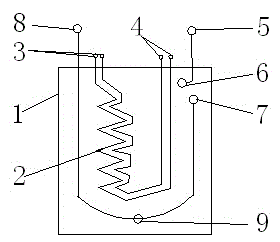
[0009] refer to figure 1 , a multi-tube heat recovery type gas-liquid separator, including a gas-liquid separator main body 1, a multi-tube heat recovery device 2 is installed in the gas-liquid separator main body 1, and the multi-tube heat recovery device 2 consists of two Or two or more copper tubes, one end of each copper tube is provided with a multi-tube medium recovery device outlet 3, and the other end of each copper tube is provided with a heat recovery device liquid inlet 4, the multi-tube medium The air outlet 3 of the recovery device and the liquid inlet 4 of the heat recovery device communicate with each other, and the main body 1 of the gas-liquid separator is provided with a first air inlet 5, a first air outlet 6, an air-liquid separator air inlet 7, The gas-liquid separator gas outlet 8, the first air inlet 5 and the first gas outlet 6 communicate with each other through a pipeline, and the gas-liquid separator gas inlet 7 and the gas-liquid separator gas outl...


PUM


Abstract

Disclosed in the invention is a multi-tube heat recovery type gas-liquid separation device comprising a main gas-liquid separation device body. A multi-tube heat recovery device is installed in the main gas-liquid separation device body and is formed by two or more than two copper tubes; a multi-tube medium recovery device air outlet is formed in one end of each copper tube and a heat recovery liquid inlet is formed in the other end of the copper tube; and the multi-tube medium recovery device air outlets and the heat recovery liquid inlets are mutually connected. A first air inlet, a first air outlet, a gas-liquid separation device air inlet, and a gas-liquid separation device air outlet are formed in the main gas-liquid separation device body; the first air inlet and the first air outlet are mutually connected by a pipeline; and the gas-liquid separation device air inlet and the gas-liquid separation device air outlet are mutually connected by a U-shaped pipeline and a return opening is formed in the U-shaped pipeline. The gas-liquid separation device has advantages of ingenious structural design, high safe and reliable performances, and energy conservation and power saving.

Description

technical field [0001] The invention relates to a gas-liquid separator, in particular to a multi-tube heat recovery type gas-liquid separator. Background technique [0002] At present, various models equipped with gas-liquid separators on the market only perform gas-liquid separation. As the water temperature or air temperature rises, the return air temperature also increases correspondingly, which increases the pressure and power consumption. Contents of the invention [0003] In order to overcome the above disadvantages, the present invention provides a multi-tube heat recovery gas-liquid separator with ingenious structural design, safe and reliable performance, energy saving and electricity saving. [0004] The technical solution adopted by the present invention to solve its technical problems is: [0005] A multi-tube heat recovery type gas-liquid separator, including a gas-liquid separator main body, a multi-tube heat recovery device is installed in the gas-liquid se...

Claims


Application Information

Patent Timeline
Patent Type & Authority Applications(China)
IPC IPC(8): F25B43/00
CPCF25B43/00
Inventor 王子忠
Owner 王子忠
Why Eureka
Try Eureka