Comprehensive Utilization System of Exhaust Gas Waste Heat of Ring Cooler

A ring cooler and waste heat technology, which is applied in waste heat treatment, mechanical equipment, steam engine devices, etc., can solve the problems of ring cooler frame deformation, ring cooler operating environment deterioration, energy waste, etc., to reduce exhaust gas temperature and improve efficiency Utilization rate, effect of increasing power generation

Active Publication Date: 2018-07-31
HUATIAN ENG & TECH CORP MCC
View PDF6 Cites 0 Cited by
  • Summary
  • Abstract
  • Description
  • Claims
  • Application Information

AI Technical Summary

Problems solved by technology

This scheme can produce considerable economic benefits, and because the exhaust gas realizes a closed cycle, which effectively avoids the environmental pollution caused by the emission of particulate matter in the exhaust gas, it has become the most mainstream waste heat recovery method for annular coolers at present, but the scheme There are still major deficiencies: First, the exhaust gas temperature at the outlet of the waste heat boiler is still as high as about 150°C, and the higher return air temperature will have an adverse effect on the operation of the ring cooler: the higher cooling air temperature of the ring cooler will lead to the failure of the ring cooler. The deterioration of the operating environment will lead to easy damage to the dynamic and static seals, accelerate the deformation of the frame of the annular cooler, and cracks in the joints of the annular cooler; secondly, because the cooling air volume of the annular cooler is very large, the exhaust gas at the outlet of the waste heat boiler at about 150 °C contains Huge sensible heat resource, the sensible heat resource still has great usable value. If it is directly returned to the ring cooler in the conventional way, although the flue gas temperature in the high temperature section of the ring cooler can be increased to increase the output of the waste heat boiler to a certain extent , but there is still a large energy waste

Method used


Image

  • Comprehensive Utilization System of Exhaust Gas Waste Heat of Ring Cooler

Examples


Embodiment 1

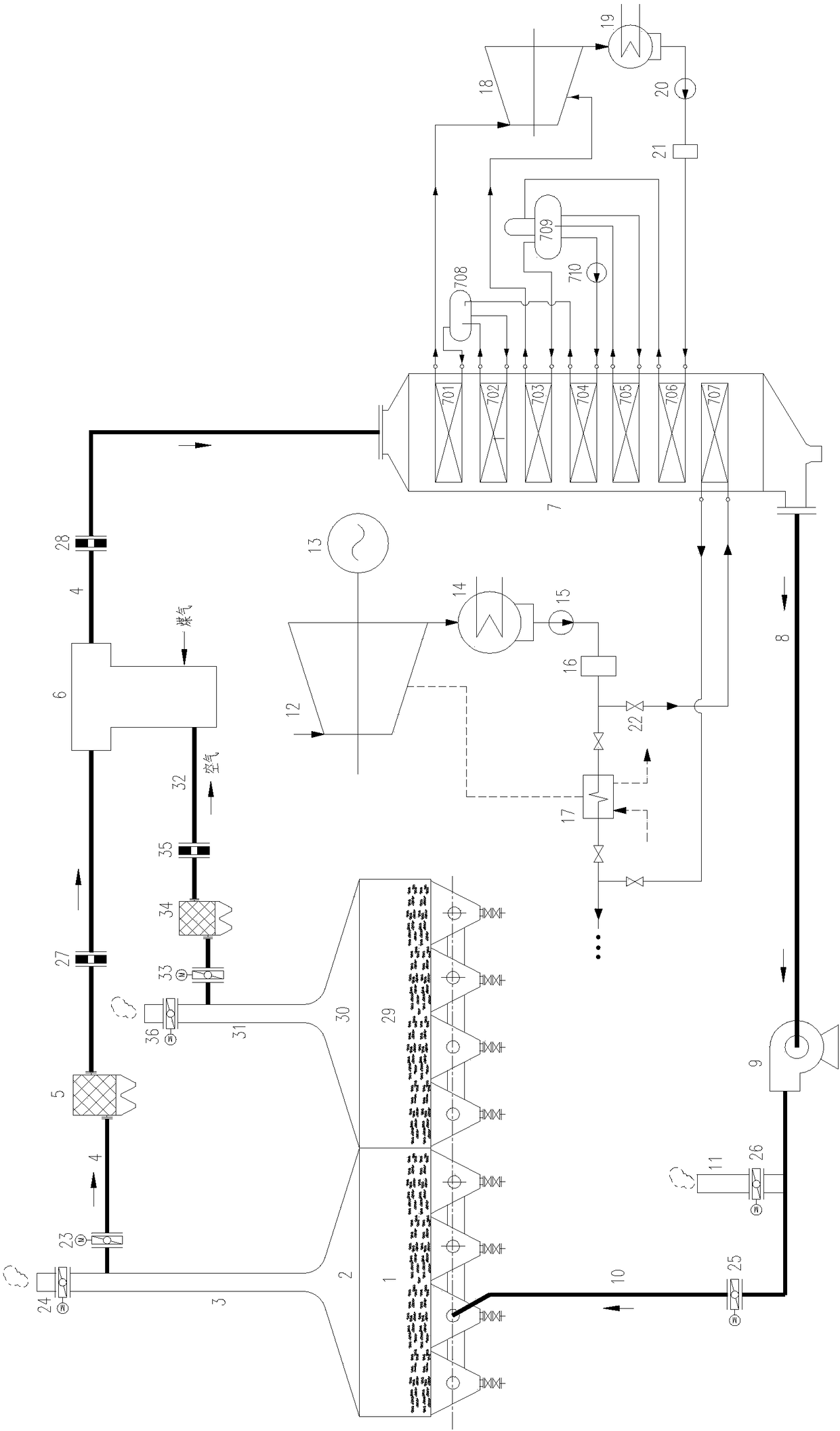
[0031] Such as figure 1 As shown, the exhaust gas waste heat comprehensive utilization system of the annular cooler in this embodiment includes a flue gas circulation system; The high-temperature chimney 3 on the cover 2 and the waste heat boiler 7 for recovering waste heat; the flue gas inlet and flue gas outlet of the waste heat boiler 7 are respectively connected with the high-temperature chimney 3 and the return air duct 10 of the ring cooler, and the return air The air duct 10 communicates with the conventional waste heat recovery section 1 of the annular cooler;

[0032] The flue of the waste heat boiler 7 is provided with a high-pressure section superheater 701, a high-pressure section evaporator 702, a low-pressure section superheater 703, a high-pressure section economizer 704, a low-pressure section evaporator 705, and a low-pressure section along the flue gas flow direction. An economizer 706 and a condensate heater 707, and a high-pressure section drum 708 and a l...

Embodiment 2

[0047] On the basis of the above-mentioned embodiments, the flue gas inlet of the waste heat boiler 7 communicates with the high-temperature chimney 3 through a conventional air intake pipe 4, and the conventional air intake pipe 4 is sequentially provided with the first A deduster 5, a first flow meter 27 and an afterburning furnace 6.

[0048] The first dust collector 5 is used to remove the particles brought in from the annular cooler in the conventional air intake pipe 4; the post-combustion furnace 6 is located between the dust collector and the waste heat boiler 7, and is used to adjust the flue gas parameters entering the waste heat boiler 7; In the embodiment, the flue gas condition of the exhaust gas waste heat recovery system is stabilized through the setting of the post-combustion furnace 6, the problem of frequent fluctuating flue gas parameters in the traditional method of directly recovering the waste gas waste heat of the annular cooler is solved, and the perform...

Embodiment 3

[0050] On the basis of the above embodiments, the low temperature section 29 of the annular cooler of the present embodiment is provided with a gas collecting hood 30, and the gas collecting hood 30 is provided with a low temperature chimney 31; the low temperature chimney 31 passes through the low temperature air intake pipe 32 It communicates with the air inlet of the supplementary combustion furnace 6, and the gas inlet of the supplementary combustion furnace 6 communicates with the gas pipeline; the low-temperature air intake pipeline 32 is provided with a second dust collector 34 and a second flow rate along the flue gas flow direction. meter 35, the flue gas inlet of the waste heat boiler 7 is also provided with a third flow meter 28, the outlet of the low-temperature chimney is provided with a fifth flue air valve 36, and the entrance of the low-temperature air intake pipe is provided with a sixth flue air valve Valve 33.

[0051] The exhaust gas waste heat comprehensiv...


PUM


Abstract

The invention discloses a system for comprehensive utilization of exhaust gas and waste heat of an annular cooler, which includes a flue gas circulation system; the flue gas circulation system includes a smoke collection hood, a high-temperature chimney and a waste heat boiler; The air duct is connected; the flue of the waste heat boiler is equipped with a high-pressure section superheater, a high-pressure section evaporator, a low-pressure section superheater, a high-pressure section economizer, a low-pressure section evaporator, a low-pressure section economizer, and a condensate heater. A high-pressure section drum and a low-pressure section drum are arranged outside the flue; the water inlet of the low-pressure section economizer is connected with the water outlet of the waste heat utilization unit, and the steam outlet of the low-pressure section superheater and the high-pressure section superheater steam outlet are connected with the waste heat utilization unit steam inlet. The water inlet of the condensate heater is connected with the water inlet of the low-pressure heater of the thermal system of the generator set, and the water outlet of the condensate heater is connected with the water outlet of the low-pressure heater of the thermal system. The invention can improve the comprehensive utilization efficiency of the waste heat of the annular cooler.

Description

technical field [0001] The invention relates to the technical field of energy saving in the iron and steel industry, in particular to a comprehensive utilization system for exhaust gas and waste heat of an annular cooler. Background technique [0002] Among the various processes of iron and steel production, the sintering process is a major energy consumer, and its energy consumption is second only to the iron-making process. The sintering ring cooler is the post-processing equipment of the sintering process, which is used to cool the temperature of the sintered ore to below 150°C. The high-temperature exhaust gas of the annular cooler is a valuable waste heat resource. Taking the annular cooler equipped with a conventional 198m2 sintering machine as an example, the flow rate of the high-temperature exhaust gas (temperature about 350-450°C) in the annular cooler section is as high as 200,000 Nm3 / h, if you can make full use of the waste heat of the exhaust gas of the annula...

Claims


Application Information

Patent Timeline
Patent Type & Authority Patents(China)
IPC IPC(8): F27D17/00F27D15/02F01K11/02F01D15/10F01D15/08
CPCF01D15/08F01D15/10F01K11/02F27D15/0286F27D17/001F27D17/004F27D2017/006Y02P10/25
Inventor 江文豪
Owner HUATIAN ENG & TECH CORP MCC
Why Eureka
Try Eureka