Sintering Ring Refrigerator Exhaust Gas Waste Heat Recovery and Utilization System

A sintered ring cooler and waste heat recovery technology, applied in waste heat treatment, steam generation method using heat carrier, climate sustainability, etc., can solve problems such as deterioration of the operating environment of the ring cooler, unfavorable use of waste heat, and energy waste. Achieve the effects of ensuring safe and stable operation, reducing the amount of regenerative steam extraction, and improving operating conditions

Active Publication Date: 2018-10-02
HUATIAN ENG & TECH CORP MCC
View PDF5 Cites 0 Cited by
  • Summary
  • Abstract
  • Description
  • Claims
  • Application Information

AI Technical Summary

Problems solved by technology

This scheme can produce considerable economic benefits, and because the exhaust gas realizes a closed cycle, which effectively avoids the environmental pollution caused by the emission of particulate matter in the exhaust gas, it has become the most mainstream waste heat recovery method of the annular cooler at present, but the scheme There are still major deficiencies: First, the exhaust gas temperature at the outlet of the waste heat boiler is still as high as about 150°C. The deterioration of the operating environment will lead to easy damage to the dynamic and static seals, accelerate the deformation of the frame of the annular cooler, and cracks in the joints of the annular cooler; secondly, because the cooling air volume of the annular cooler is very large, the exhaust gas at the outlet of the waste heat boiler at about 150 °C contains Huge sensible heat resource, the sensible heat resource still has great usable value. If it is directly returned to the ring cooler in the conventional way, although the flue gas temperature in the high temperature section of the ring cooler can be increased to increase the output of the waste heat boiler to a certain extent , but there is still a large energy waste
[0004] In addition, when the fume collecting hood on the ring cooler collects high-temperature gas, the collection process of high-temperature gas is an unstable process due to the operation of the trolley, and the instability of high-temperature gas leads to instability in the process of waste heat utilization The situation is not conducive to the utilization of waste heat

Method used


Image

  • Sintering Ring Refrigerator Exhaust Gas Waste Heat Recovery and Utilization System

Examples


Embodiment 1

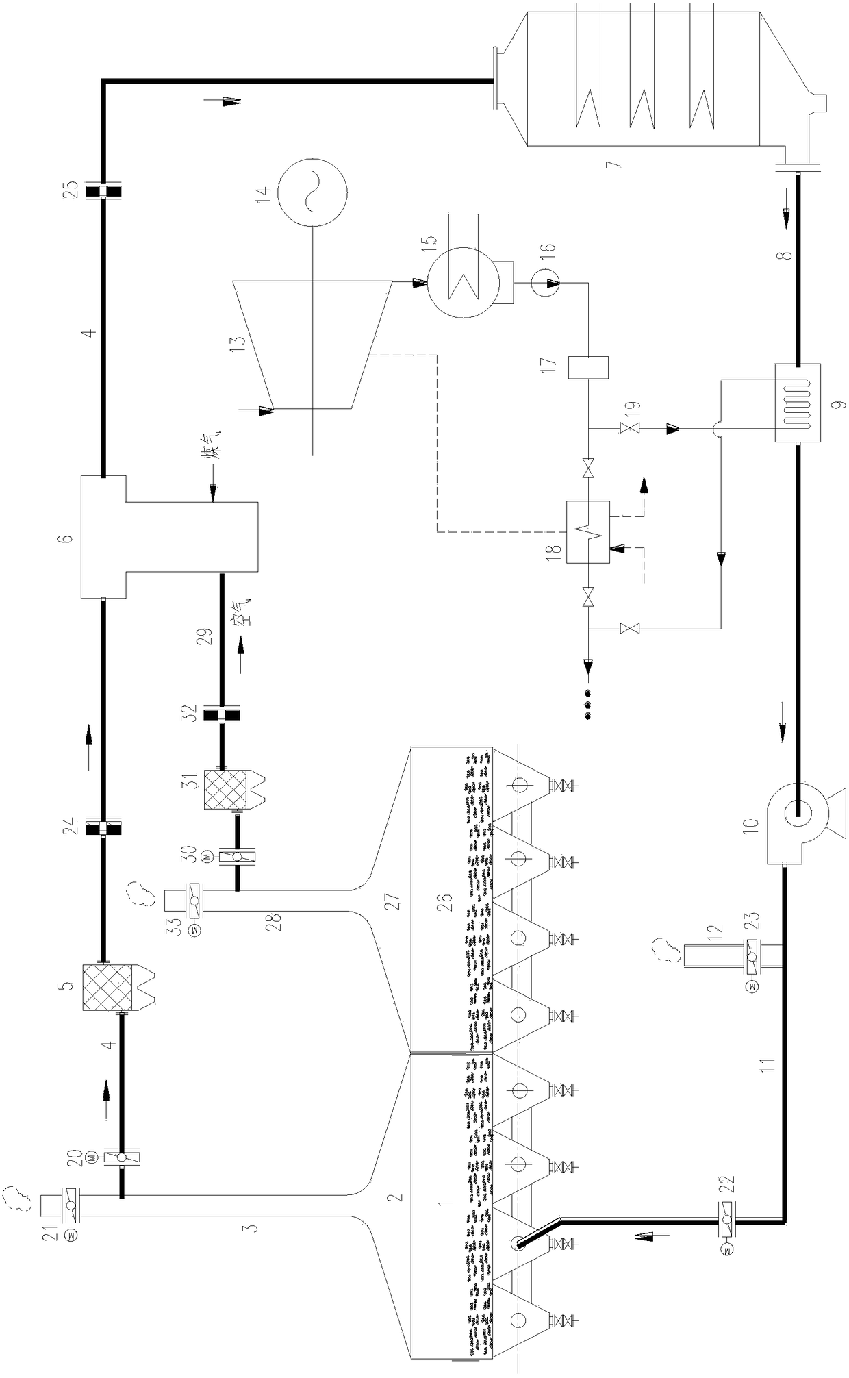
[0028] Such as figure 1 As shown, the exhaust gas waste heat recovery and utilization system of the sintering ring cooler in this embodiment includes a conventional flue gas circulation system;

[0029] The flue gas circulation system includes a conventional waste heat recovery section 1 of the annular cooler, a smoke collection hood 2 arranged above the conventional waste heat recovery section 1 of the annular cooler, a high-temperature chimney 3 arranged on the smoke collection hood 2 and a waste heat recovery Waste heat boiler 7; the high-temperature chimney 3 and the flue gas inlet of the waste heat boiler 7 are connected through a conventional air intake pipe 4, the flue gas outlet of the waste heat boiler 7 is connected with a smoke exhaust pipe 8, and the conventional waste heat of the annular cooler The air return port of the recovery section 1 is connected with a return air duct 11, and the exhaust duct 8 communicates with the return air duct 11; the exhaust duct 8 of...

Embodiment 2

[0052] On the basis of the above embodiments, the conventional air intake duct 4 is provided with a first dust remover 5, the first dust remover 5 and the afterburning furnace 6 are sequentially arranged along the flow direction of the flue gas, and the low temperature chimney 28 communicates with the air inlet of the post-combustion furnace 6 through a low-temperature air intake pipe 29, and a second dust collector 31 is arranged on the low-temperature air intake pipe 29.

[0053] Dust collectors are arranged on the low-temperature air intake pipeline 29 and the conventional air intake pipeline 4 to remove the particulate matter carried out in the flue gas, which can reduce the deposition of particulate matter in the pipeline and avoid pipeline blockage due to excessive particulate matter deposition. At the same time, the particulate matter When running in the pipeline, the pipeline will also be worn, and the removal of particulate matter can reduce the wear on the pipeline an...

Embodiment 3

[0055] On the basis of the above embodiments, the inlet and outlet of the flue gas-condensed water heat exchanger 9 and the inlet and outlet of the low-pressure heater group 18 are respectively provided with control valves 19 .

[0056] The exhaust gas waste heat recovery and utilization system of the sintering ring refrigerator in this embodiment can realize the adjustment of the ratio of the heat provided by the low pressure heater group 18 and the flue gas-condensed water heat exchanger 9 to the generator set by adjusting the opening degree of the control valve 19 The switching operation of the low-pressure heater group 18 and the flue gas-condensed water heat exchanger 9 is realized through the switch of the valve.


PUM


Abstract

The invention discloses a waste heat recovery and utilization system of a sintering ring cooler exhaust gas, which includes a conventional flue gas circulation system; the flue gas circulation system includes a conventional waste heat recovery section of the ring cooler, a smoke collection hood, a high-temperature chimney and a waste heat boiler; a high-temperature chimney and a waste heat boiler The flue gas inlet is connected, and the flue gas outlet of the waste heat boiler is connected with the return air pipe of the conventional waste heat recovery section of the annular cooler; the flue gas-condensed water heat exchanger is installed on the exhaust pipe of the waste heat boiler; the supplementary combustion furnace is installed on the conventional air intake pipe , the air inlet of the supplementary combustion furnace is connected with the low-temperature air intake pipe, the low-temperature air intake pipe is connected with the low-temperature chimney, the low-temperature chimney is connected with the gas collection hood, and the gas collection hood is set on the low-temperature section of the ring cooler; the water inlet of the waste heat boiler is connected with the waste heat utilization unit The water outlet is connected, the steam outlet of the waste heat boiler is connected with the steam inlet of the waste heat utilization unit; the flue gas-condensed water heat exchanger is connected in parallel with the heater group of the thermal system of the generating unit. The invention can improve the comprehensive utilization rate of the waste heat recovery of the annular cooler.

Description

technical field [0001] The invention relates to a system for recovering and utilizing waste heat of exhaust gas of a sintering ring cooler. Background technique [0002] Among the various processes of iron and steel production, the sintering process is a major energy consumer, and its energy consumption is second only to the iron-making process. The sintering ring cooler is the post-processing equipment of the sintering process, which is used to cool the temperature of the sintered ore to below 150°C. The high-temperature exhaust gas of the annular cooler is a valuable waste heat resource. Taking the annular cooler equipped with a conventional 198m2 sintering machine as an example, the flow rate of the high-temperature exhaust gas (temperature about 350-450°C) in the annular cooler section is as high as 200,000 Nm3 / h, if you can make full use of the waste heat of the exhaust gas of the annular cooler, you will be able to reap very considerable economic benefits. [0003] ...

Claims


Application Information

Patent Timeline
Patent Type & Authority Patents(China)
IPC IPC(8): F27D17/00F22B1/18
CPCF22B1/18F27D17/001F27D17/004F27D2017/006Y02P10/25Y02P80/15
Inventor 江文豪
Owner HUATIAN ENG & TECH CORP MCC
Why Eureka
Try Eureka