
Heating structure and heating method of boiler based on partitioned flue and multistage air preheating

A technology for separating the flue and air preheating, which is applied to steam boilers, combustion methods, lighting and heating equipment, etc., can solve the problems that the heat released by the flue gas cannot be effectively used, the temperature utilization space is limited, and there is no consideration for restrictions, etc., to achieve reduction The effect of reheating and extracting steam, reducing coal consumption and increasing air temperature

Active Publication Date: 2015-04-15
山东汉思非晶材料科技有限公司
View PDF7 Cites 0 Cited by
  • Summary
  • Abstract
  • Description
  • Claims
  • Application Information

AI Technical Summary

Problems solved by technology

[0005] At present, it is suitable to use the waste heat of flue gas at the tail of the boiler directly to use the low-temperature flue gas at the outlet of the air preheater to heat the condensed water. Since the exhaust gas temperature of the air preheater is about 120-140 °C, the temperature utilization space is limited and the form is single.
And it does not take into account the constraints brought by the structural arrangement of the heating surface at the rear of the boiler to the utilization of waste heat of the flue gas, so that the heat released by the flue gas cannot be effectively utilized in an optimized form

Method used


Image

  • Heating structure and heating method of boiler based on partitioned flue and multistage air preheating

Examples


Embodiment Construction

[0021] The present invention provides a boiler heating structure and heating method based on separated flue and multi-stage air preheating, which will be further described below in conjunction with the accompanying drawings and specific embodiments.

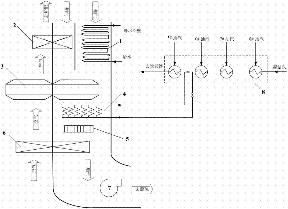
[0022] figure 1 It is a schematic diagram of the structure of the present invention. In the front section of the flue at the tail of the boiler, a partition plate is used to divide the flue into two paths. Economizer 1 and high-temperature air preheater 2 are respectively arranged on both sides of the partition plate. The main air preheater 3, flue gas-condensed water heat exchanger 4, dust collector 5, front air preheater 6, and blower 7 are arranged in sequence in the tunnel.

[0023] This system uses the waste heat of the flue gas to heat the hot air entering the furnace and part of the low-pressure condensed water. The principle is as follows; the tail flue is divided into two parts: the separated flue and the main flue. Th...


PUM


Abstract

The invention provides a heating structure and a heating method of a boiler based on a partitioned flue and multistage air preheating and belongs to the field of power station energy-saving equipment. A partition board is arranged on the front part of rear flue of the boiler, thus the flue is partitioned into two paths, an economizer and a high temperature air pre-heater are respectively arranged on the two sides of the partition board, and an air pre-heater, a flue gas-condensation water heat exchanger, a dust remover, a front-load air pre-heater and a blower are arranged in a main flue behind a flue partition part in sequence. Flue gas of 450-500 DEG C in a boiler tail enters into the economizer and the high temperature air pre-heater simultaneously, outlet flue gas mixes in the main flue and enters into follow-up equipment in sequence, and is expelled from the system till the temperature of the flue gas is reduced to 80-100 DEG C. By means of the heating structure and the heating method of the boiler based on a partitioned flue and multistage air preheating, on the one hand, pulverized coal combustion and particularly stable combustion in low load are strengthened, on the other hand, air temperature of an air side is increased and regenerative extraction flow of steam of a condensation water side is reduced by using the waste heat of the flue gas, thus unit coal consumption is reduced, energy-saving benefit is achieved, and therefore the waste heat of the flue gas can be used under the optimality condition.

Description

technical field [0001] The invention belongs to the field of power station energy-saving equipment, in particular to a boiler heating structure and heating method based on separated flue and multi-stage air preheating. Background technique [0002] In my country, coal-fired power plants consume nearly half of the country's coal production. With the continuous rise of coal energy prices in recent years, the cost of coal-based power generation is increasing. All thermal power plants are facing huge energy-saving pressure and are constantly seeking to reduce Coal consumption, new technologies applied in energy conservation, and increase related capital investment. [0003] In order to avoid acid dew point corrosion on the heating surface at the tail, the exhaust gas temperature of boilers in thermal power plants is generally around 120-130 °C; for boilers burning high-sulfur fuel, the exhaust gas temperature is raised to about 150 °C; add heaters The exhaust gas temperature of ...

Claims


Application Information

Patent Timeline
Patent Type & Authority Patents(China)
IPC IPC(8): F22B31/08F23L15/00
CPCY02E20/34
Inventor 徐钢许诚杨勇平方亚雄薛志勇王永田
Owner 山东汉思非晶材料科技有限公司
Learn More