

Vacuum valve
A vacuum valve and vacuum technology, applied in the direction of sliding valve, valve details, valve device, etc., can solve the problem of expensive vacuum valve processing, and achieve the effect of saving materials
- Summary
- Abstract
- Description
- Claims
- Application Information
AI Technical Summary
Problems solved by technology
Method used
Image

Examples
Embodiment Construction
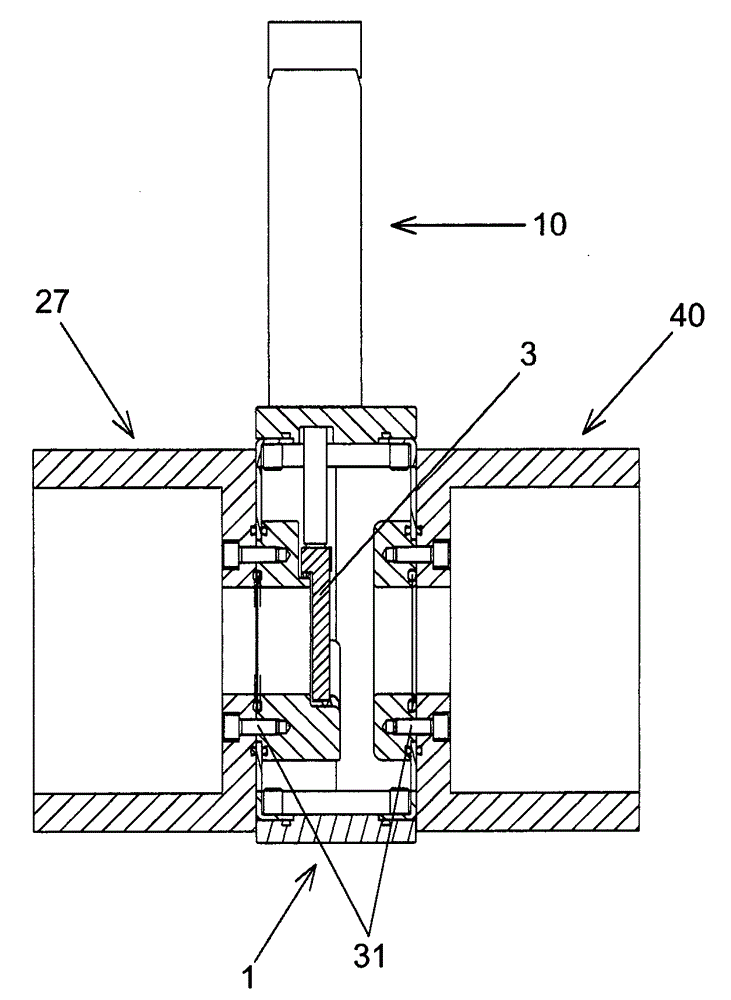
[0033] exist Figures 1 to 14 A first embodiment of a vacuum valve according to the invention is shown in .
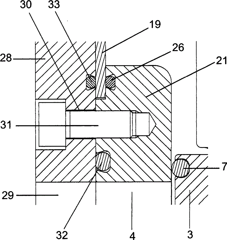
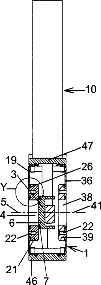
[0034] The vacuum valve has a valve housing 1 with an inner chamber 2 in which, in the exemplary embodiment, a plate-shaped closing body 3 is arranged.
[0035] In the closed state of the vacuum valve shown in the drawing, the valve opening 4 of the valve housing, which has an axis 5 , is closed by the closing body 3 . To this end, the closing body 3 presses against the valve seat 6 surrounding the valve opening 4 . In the exemplary embodiment described, an elastic seal 7 is arranged on the closing body 6 , which bears against the sealing surface of the valve seat 6 . In a modified embodiment, the seal can also be arranged on the valve seat 6 and the sealing surface on the closing body 3 .
[0036] In the closed state of the vacuum valve, the closing body 3 assumes the closed position shown in the drawing.
[0037] In the open state of the vacuum valve, the valve o...
PUM
| Property | Measurement | Unit |
|---|---|---|
| Thickness | aaaaa | aaaaa |
| Thickness | aaaaa | aaaaa |
Abstract
Description
Claims
Application Information