
Auxiliary feeding apparatus of extruder

An extruder and material feeding technology, applied in the industrial field, can solve problems such as affecting production quality and inconsistency in proportion of easy photos, and achieve the effect of improving work efficiency and product quality

Inactive Publication Date: 2015-08-19
苏州普勒新材料有限公司
View PDF5 Cites 0 Cited by
  • Summary
  • Abstract
  • Description
  • Claims
  • Application Information

AI Technical Summary

Problems solved by technology

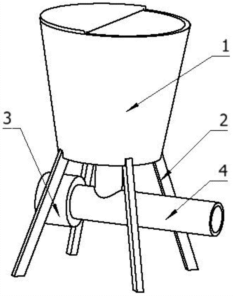
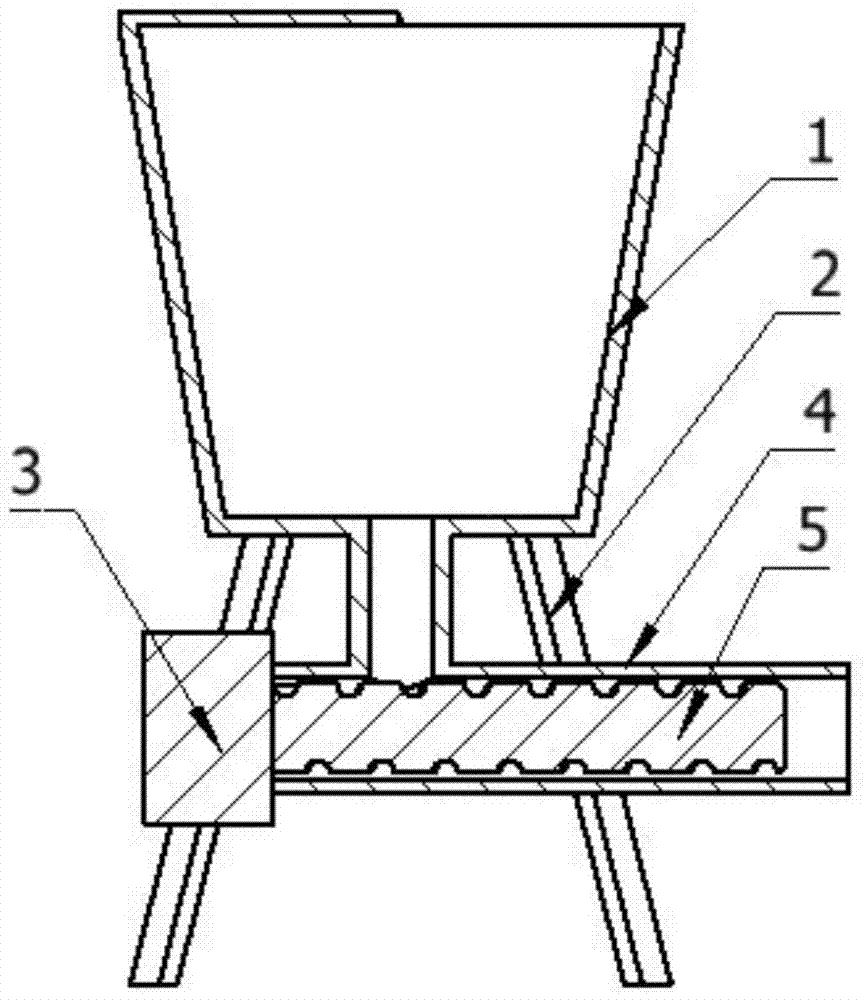
[0002] In the paint industry, some materials cannot be directly put into the feed port of the extruder during the production of the extruder. At this time, it is necessary to use a feeder for feeding, such as Figure 1-2 As shown, the existing feeder includes a vertically placed barrel; the lower end of the barrel is provided with a T-shaped feed pipe and three circumferentially placed supports; the feed pipe is provided with a horizontally placed and rotatable screw rod; One end of the screw is provided with a motor; when working, the material falls into the feeding pipe by its own gravity, and is extruded and put in through the screw in the feeding pipe; in actual work, some materials are very light and cannot be dropped by their own gravity. It is extruded by the screw in the feeding pipe, and the material can only be put into the extruder manually, which is easy to be inconsistent in proportion and affects the production quality. Therefore, we have developed an auxiliary extruder that can add lighter materials. The feeding device can adjust the quantity of feeding materials, thus improving work efficiency and product quality

Method used


Image

  • Auxiliary feeding apparatus of extruder
  • Auxiliary feeding apparatus of extruder
  • Auxiliary feeding apparatus of extruder

Examples


Embodiment Construction

[0019] The present invention will be further described in detail below in conjunction with the accompanying drawings and specific embodiments.

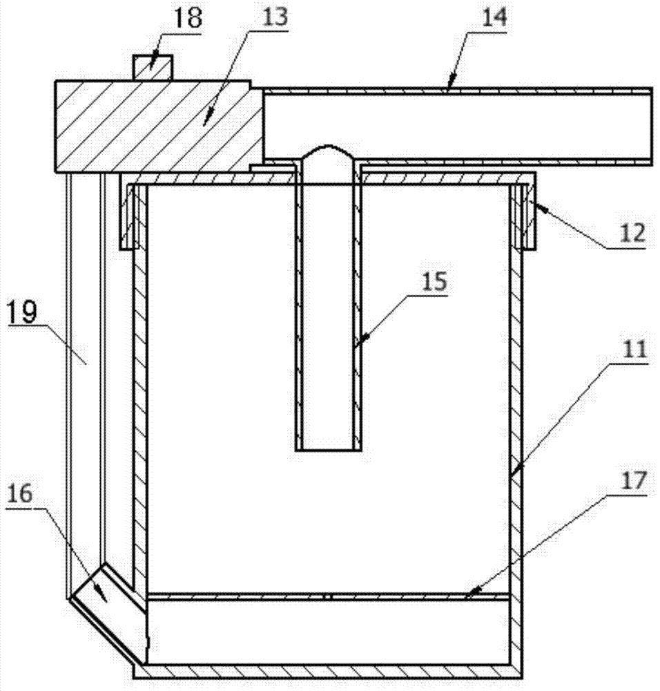
[0020] attached Figure 3-4 It is an auxiliary feeding device for the extruder of the present invention, comprising a vertically placed material cylinder 11; the upper end of the material cylinder 11 is provided with an end cover 12, and the material cylinder 11 and the end cover 12 are connected by threads; The outer lower end of the material cylinder 11 is provided with an upwardly inclined air inlet 16 to prevent the material from flowing out from the air inlet 16; above the air inlet 16 in the material cylinder 11, a support that fits the inner wall and is placed horizontally is provided. plate 17; the support plate 17 is provided with a number of evenly distributed small through holes; the center of the end cover 12 is provided with a feed pipe 15 placed vertically, and the connection between the end cover 12 and the feed pipe 15...


PUM


Abstract

The invention relates to an auxiliary feeding apparatus of an extruder. The apparatus comprises a vertically arranged material cylinder; the upper end of the material cylinder is provided with an end cover; the outside lower end of the material cylinder is provided with an air inlet; a supporting plate laminated to the inner wall is arranged above the air inlet in the material cylinder; the supporting plate is provided with a plurality of uniformly distributed through holes; the center of the end cover is provided with a feeding tube; the upper end of the feeding tube is provided with a discharging tube connected with the feeding tube; one end of the discharging tube is provided with an air pump; and the air inlet is connected with the air pump through an air tube. The air pump allows a material in the material cylinder to be in a floating state and form a negative pressure in the material cylinder, and allows the material to be sucked into the discharging tube and to be discharged through airflow, and the quantity of the fed material can be adjusted, so the work efficiency and the product quality are improved.

Description

technical field [0001] The invention relates to the industrial field, in particular to an auxiliary feeding device for an extruder. Background technique [0002] In the paint industry, some materials cannot be directly put into the feed port of the extruder during the production of the extruder. At this time, it is necessary to use a feeder for feeding, such as Figure 1-2 As shown, the existing feeder includes a vertically placed barrel; the lower end of the barrel is provided with a T-shaped feed pipe and three circumferentially placed supports; the feed pipe is provided with a horizontally placed and rotatable screw rod; One end of the screw is provided with a motor; when working, the material falls into the feeding pipe by its own gravity, and is extruded and put in through the screw in the feeding pipe; in actual work, some materials are very light and cannot be dropped by their own gravity. It is extruded by the screw in the feeding pipe, and the material can only be p...

Claims


Application Information

Patent Timeline
IPC IPC(8): B29C47/10
CPCB29C48/92B29C48/285
Inventor 袁文荣
Owner 苏州普勒新材料有限公司
Learn More