Vertical connection structure for precast concrete shear walls and construction method

A concrete shear wall and shear wall technology, which is applied to building structures, walls, building components, etc., can solve the problems of easy cracking of the protective layer at the opening, high cost of sleeves and grouting materials, and large amount of grouting materials. problems, achieve the effect of reducing the weight of the wall, making the connection less difficult, and preventing the hole wall from cracking

Active Publication Date: 2015-08-19
吉林长发建筑产业化有限公司
View PDF6 Cites 24 Cited by
  • Summary
  • Abstract
  • Description
  • Claims
  • Application Information

AI Technical Summary

Benefits of technology

This patented technology reduces the size of holes on walls while maintaining their strength without adding extra parts like reinforcement rods that are expensive compared to normal building components such as bricks. It also prevents cracks caused by external forces during installation due to reduced thicknesses at both ends. Additionally, it eliminates the need for specialized equipment used when constructing buildings because there's no need to put them inside after assembly instead they just go around. Overall, this innovative design improving safety measures against damage and reducing manufacturing cost makes possible new constructions more efficient than traditional methods.

Problems solved by technology

This patented technical problem addressed in this patents relates to connecting thickened materials like cement or mortars during construction without requiring expensive equipment such as metal rods that can be easily damaged due to their length.

Method used


Image

  • Vertical connection structure for precast concrete shear walls and construction method
  • Vertical connection structure for precast concrete shear walls and construction method
  • Vertical connection structure for precast concrete shear walls and construction method

Examples


Embodiment Construction

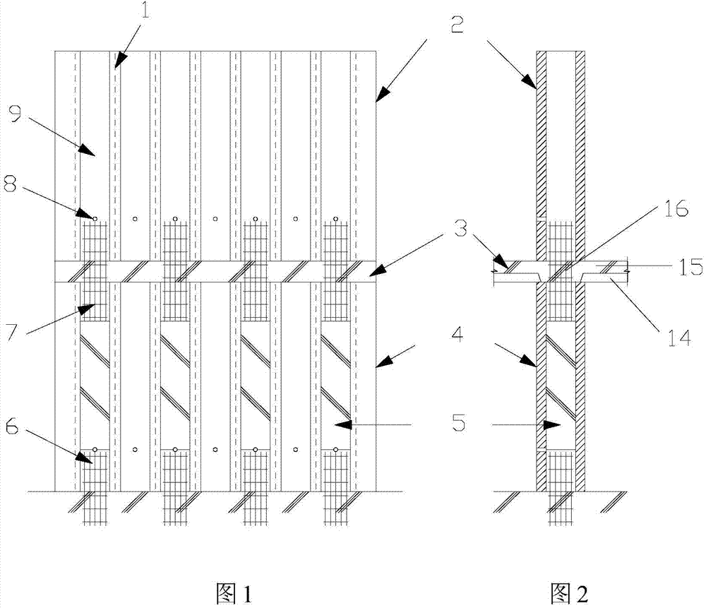
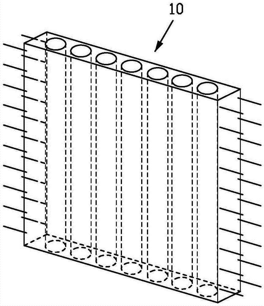
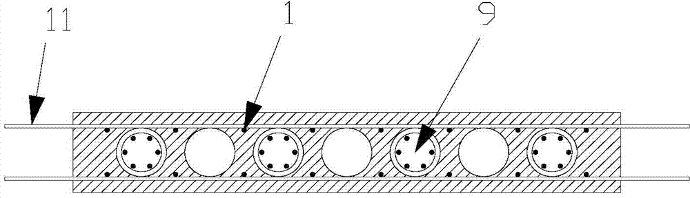
[0031] Such as Figure 1 to Figure 6 As shown, the vertical connection structure of the prefabricated concrete shear wall of the present invention mainly includes: vertically distributed steel bars 1, upper prefabricated porous shear wall 2, floor slab 3, lower prefabricated porous shear wall 4, cast-in-situ concrete or pouring mortar or Other filling materials 5, cast-in-place concrete or pouring mortar 6, connecting reinforcement cage 7, cast-in-place concrete or pouring mortar confirmation hole 8, vertical through hole 9, prefabricated porous shear wall 10, horizontal distribution reinforcement 11, vertical connecting bar 12. Spiral rib or ring rib 13, etc., the specific structure is as follows:

[0032] The prefabricated porous shear wall 10 comprises an upper prefabricated porous shear wall 2 and a lower prefabricated porous shear wall 4, and between the upper prefabricated porous shear wall 2 and the lower prefabricated porous shear wall 4 is a floor 3 (prefabricated flo...


PUM


Abstract

The invention relates to the field of precast concrete structures, in particular to a vertical connection structure for precast concrete shear walls and a construction method. Steel bars in vertical distribution and steel bars in horizontal distribution are arranged on two sides of each vertical through hole of each precast porous shear wall which is a porous hollow wall. At a construction site, vertical connection between an upper precast porous shear wall and a lower precast porous shear wall is realized by arranging connection reinforcement cages and concreting or grouting mortar into floor cast-in-situ zones and vertical through holes of the precast porous shear walls. By the shear wall and the connection method, dead weight of a wall body is reduced, and cost is reduced as compared with that of a reinforcement sleeve grouting connection method. Compared with an existing core-pulled porous hoop-confined concrete reinforcement grouting anchor lap joint method or a metal corrugated tube porous reinforcement grouting anchor lap joint method, the vertical connection method has the advantages that hole quantity is reduced to prevent cracking of porous walls, and transport is facilitated due to the fact that the vertical steel bars in the precast walls do not protrude outside.

Description


Claims


Application Information

Patent Timeline
Owner 吉林长发建筑产业化有限公司
Why Eureka
Try Eureka