
Semi-transparent and semi-covered panel, touch panel and manufacturing methods of semi-transparent and semi-covered panel and touch panel as well as display device

A manufacturing method and touch panel technology, which are applied in the photoengraving process, optics, optomechanical equipment and other directions of the pattern surface, and can solve the problems of residue, uneven color of semi-transparent and semi-shielding panels, etc.

Active Publication Date: 2015-08-19
BOE TECH GRP CO LTD
View PDF5 Cites 7 Cited by
  • Summary
  • Abstract
  • Description
  • Claims
  • Application Information

AI Technical Summary

Problems solved by technology

[0004] However, when the formed white photoresist 02 is relatively thick, a trapezoidal white photoresist 02 will be formed after the first exposure and development. After the second exposure and development, since the black photoresist 03 accumulates on the edge of the white photoresist 02, it is difficult to wash off the black photoresist 03 at the edge of the white photoresist 02, which results in residues at the edge of the white photoresist 02 There is a problem with black photoresist 03, which leads to uneven color on the translucent panel

Method used


Image

  • Semi-transparent and semi-covered panel, touch panel and manufacturing methods of semi-transparent and semi-covered panel and touch panel as well as display device
  • Semi-transparent and semi-covered panel, touch panel and manufacturing methods of semi-transparent and semi-covered panel and touch panel as well as display device
  • Semi-transparent and semi-covered panel, touch panel and manufacturing methods of semi-transparent and semi-covered panel and touch panel as well as display device

Examples


Embodiment Construction

[0040] In the following description, for purposes of illustration rather than limitation, specific details, such as specific system architectures, interfaces, and techniques, are set forth in order to provide a thorough understanding of the present invention. It will be apparent, however, to one skilled in the art that the invention may be practiced in other embodiments without these specific details. In other instances, detailed descriptions of well-known devices, circuits, and methods are omitted so as not to obscure the description of the present invention with unnecessary detail.

[0041] In addition, the terms "first" and "second" are used for descriptive purposes only, and cannot be understood as indicating or implying relative importance or implicitly specifying the quantity of indicated technical features. Thus, a feature defined as "first" and "second" may explicitly or implicitly include one or more of these features. In the description of the present invention, unl...


PUM


Abstract

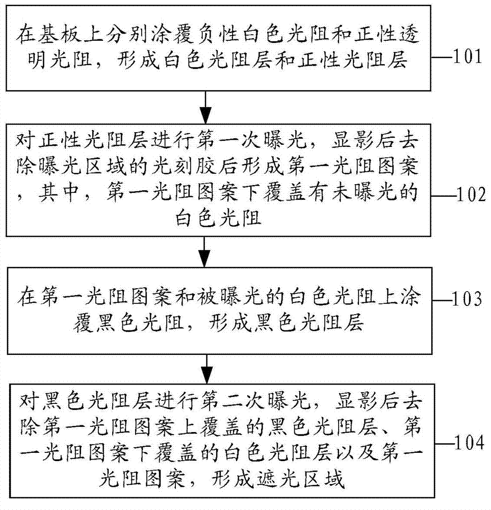
The embodiment of the invention provides a semi-transparent and semi-covered panel, a touch panel and manufacturing methods of the semi-transparent and semi-covered panel and the touch panel as well as a display device, and relates to the technical field of display, aiming at solving the problem that the color of a white touch panel is not uniform. The manufacturing method of the semi-transparent and semi-covered panel comprises the steps of enabling a substrate to be respectively coated with a negative white light resistance and a positive transparent light resistance to form a white light resistance layer and a positive light resistance layer; exposing the positive light resistance layer for the first time, developing, and then removing photoresist at the exposure range to form a first light resistance pattern, wherein an unexposed white light resistance is covered by the first light resistance pattern; enabling the first light resistance pattern and the exposed white light resistance to be coated with a black light resistance to form a black light resistance layer; exposing the black light resistance layer for a second time, developing, and then removing the black light resistance layer covering the first light resistance pattern, the white light resistance layer covered by the first light resistance pattern, and the first light resistance pattern to form a shading area. The method can be applied to the manufacturing process of the touch panel.

Description

technical field [0001] The present invention relates to the field of display technology, in particular to a semi-transparent panel, a touch panel, a manufacturing method thereof, and a display device. Background technique [0002] OGS (One Glass Solution, monolithic glass) touch panel, that is, the conductive film and sensors are directly formed on the semi-transparent panel, so that the semi-transparent panel can simultaneously protect the internal structural glass and the touch sensor. . Among them, according to the color of the shading area, the semi-transparent panel can be divided into: a black semi-transparent panel made of black color resistance, and a white semi-transparent panel made of white color resistance. [0003] For white translucent panels such as figure 1 As shown, the white photoresist 02 is set on the glass substrate 01. Since the optical density value of the white photoresist is low, in order to meet the light-shielding requirements, a layer of black p...

Claims


Application Information

Patent Timeline
IPC IPC(8): G03F7/00G06F3/041
Inventor 田慧徐传祥付承宇
Owner BOE TECH GRP CO LTD
Learn More