A self-adaptive adjustable pan-tilt

A self-adaptive adjustment and pan-tilt technology, applied in waterborne ship navigation equipment, ships, navigation aid arrangements, etc., can solve the problems of complex control system, long response time, inability to reflect real-time performance, etc. Effect

Active Publication Date: 2017-09-26
精海智能装备有限公司
View PDF3 Cites 0 Cited by
  • Summary
  • Abstract
  • Description
  • Claims
  • Application Information

AI Technical Summary

Problems solved by technology

Due to the complexity of the control system and the long response time of this type of horizontal pan / tilt, it cannot reflect the real-time requirements
[0004] There are three existing related level correction devices, such as a buoyancy positioning laser line thrower involved in 03146296.0, which automatically maintains the level by simulating the hull floating on the liquid during operation. This device is only suitable for carrying small-sized and light-weight For objects, when the measuring equipment carried on the platform reaches a certain mass, according to the buoyancy generation formula, the size of the container and floating objects required to generate buoyancy will also increase accordingly to meet the balance between buoyancy and gravity; a floating platform laser involved in 201120455401.8 The level uses a floating platform to achieve level correction, and it also does not take into account the size limit of the entire device when the equipment on the platform is large; 98240111.6 involves a horizontal and vertical laser pointer device, the laser is set in the buoy, and the buoy is used to The characteristic of maintaining a constant level in the liquid surface keeps the emitted laser in a horizontal and vertical direction at all times. This device does not involve the problem of how to build a horizontal stabilization platform.

Method used


Image

  • A self-adaptive adjustable pan-tilt
  • A self-adaptive adjustable pan-tilt
  • A self-adaptive adjustable pan-tilt

Examples


Embodiment Construction

[0018] The specific embodiments of the present invention will be further described below in conjunction with the accompanying drawings.

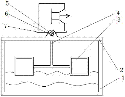
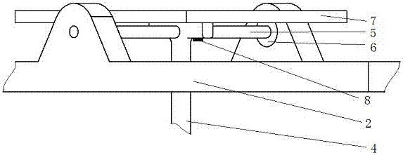
[0019] Such as figure 1 with figure 2 Shown, a kind of self-adaptive adjustable horizontal cloud platform comprises a base 1, a top cover 2, a floating block 3, a support 4, a support shaft 5, a rolling bearing 6, a cloud platform 7, and a screw 8; the base 1 is a A cuboid cavity container with an open top, the top cover 2 is located on the top of the base 1, a small opening is opened in the center of the top cover 2, there is a protrusion at the center position on both sides of the top cover 2, and a circular hole is opened in the center of the protrusion , the two rolling bearings 6 are installed in the circular hole; the two ends of the bottom of the bracket 4 are connected to two identical floating blocks 3, the top of the bracket 4 passes through the small opening in the center of the top cover 2, and is fixed by screws 8 The bottom ...


PUM


Abstract

The invention relates to a self-adaptive adjustable horizontal cloud platform, comprising a base, a top cover, a floating block, a bracket, a support shaft of the bracket, a rolling bearing, a cloud platform, and screws; the base is a cuboid cavity container with an open top, and the The top cover is located on the top of the base, a small opening is opened in the center of the top cover, and there is a protrusion at the middle position on both sides of the top cover, a circular hole is opened in the center of the protrusion, and the two rolling bearings are installed in the circular hole; Two identical floating blocks are connected at both ends of the bottom of the bracket, the top of the bracket passes through the small opening in the center of the top cover, and is fixed on the bottom of the platform by screws, and a small hole is arranged at the upper position in the middle of the bracket; The support shaft of the bracket passes through the small hole, and the two ends are inserted into the rolling bearings. Under the action of the opposite torque generated by the floating block, the present invention can automatically adjust the pan-tilt to the horizontal position, so that the operation of the equipment is not affected, and the overall size does not need to be too large, and the function of self-adaptive adjustment can be realized, which is easy to use and has good real-time performance .

Description

technical field [0001] The invention relates to an adaptively adjustable horizontal platform, which is applied to the hull of an unmanned boat on the water surface and belongs to the field of obstacle avoidance control of the unmanned boat. Background technique [0002] Since the pitch angle of the unmanned boat will change all the time when the unmanned boat is moving on the water surface, the equipment used to detect obstacles on the unmanned boat, such as the laser scanner, needs to keep its attitude level at all times, otherwise the laser beam will shoot to the water surface or the sky , it will not be able to accurately detect the obstacles directly in front of the unmanned boat, which will have a great impact on the obstacle detection of the unmanned boat. [0003] At present, most of the existing horizontal stabilization gimbal technologies use the attitude sensor carried by the ship itself to measure the attitude information such as the pitch angle of the hull in rea...

Claims


Application Information

Patent Timeline
Patent Type & Authority Patents(China)
IPC IPC(8): B63B49/00
Inventor 彭艳瞿栋罗均朱倩丁峰
Owner 精海智能装备有限公司
Why Eureka
Try Eureka