Heat dissipating device with independent air channels

A technology of a heat dissipation device and an air duct is applied in the field of heat dissipation of a heating power unit, which can solve the problems that the surface of the radiator cannot be fully passed, the applicability of high-power equipment is poor, and the cost is high. Effects that are easy to use in the field

Active Publication Date: 2013-08-14
大连美恒电气有限公司
View PDF5 Cites 0 Cited by
  • Summary
  • Abstract
  • Description
  • Claims
  • Application Information

AI Technical Summary

Problems solved by technology

The cold air is blown in from the bottom by the fan, passes through multiple power units and heat sinks, and is discharged from the air outlet on the top. This heat dissipation method has the following problems: 1. If the air is blown from the bottom, the upper exhaust will inevitably lead to the top of the power components. Some of them have falling dust, which affects the heat dissipation effect. In special working conditions, there may be conductive medium dust entering, whic

Method used


Image

  • Heat dissipating device with independent air channels
  • Heat dissipating device with independent air channels
  • Heat dissipating device with independent air channels

Examples


Embodiment Construction

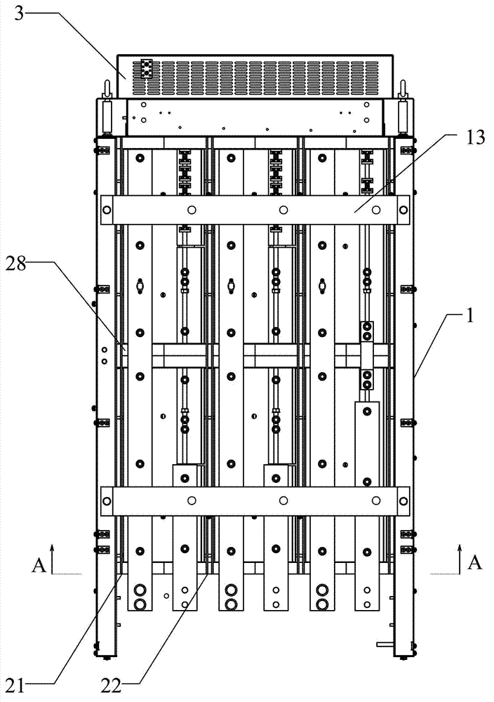
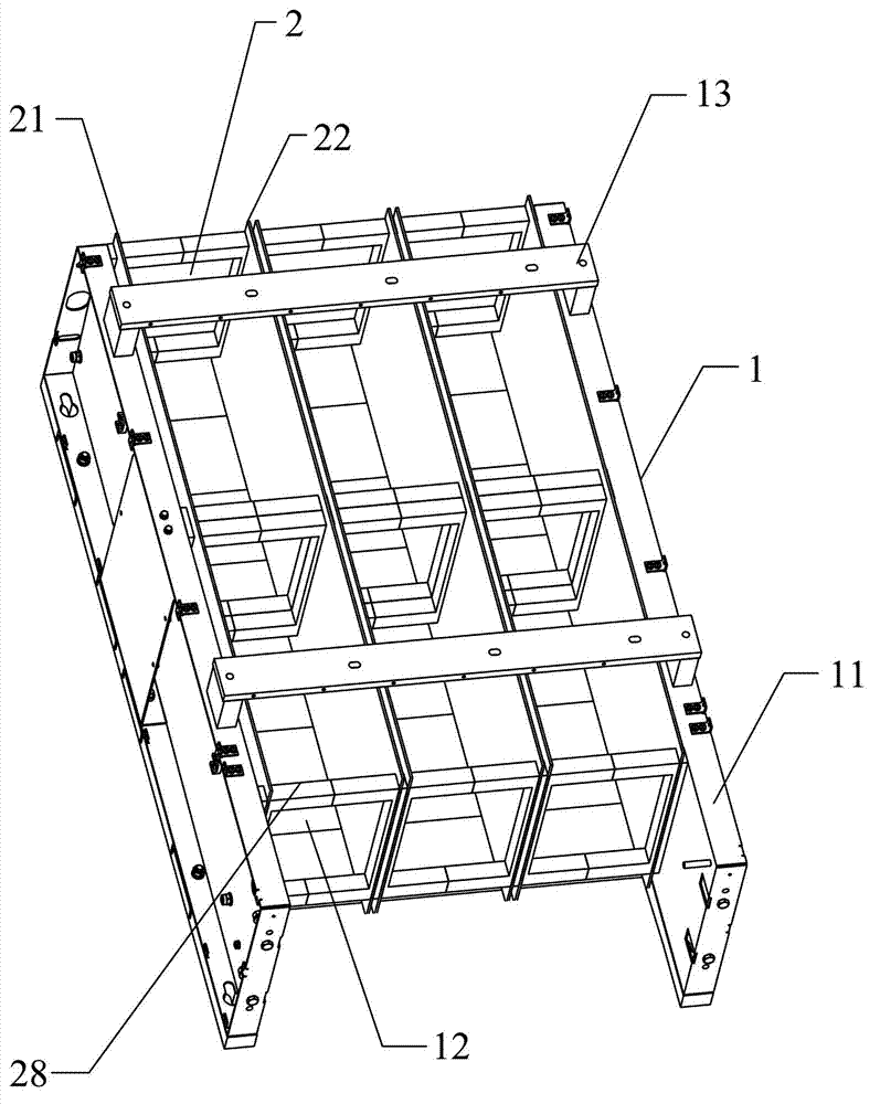
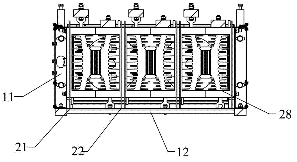
[0025] Such as figure 1 As shown, a heat dissipation device with an independent air duct includes a frame 1 and a fan unit 3, and the frame 1 (such as figure 2 , image 3 shown) includes side walls 11 on both sides and bottom fixing plates 12 connecting the side walls 11 on both sides. In this embodiment, the frame 1 is provided with three sets of Independent air duct 2, said independent air duct 2 includes two sets of heat sink groups composed of heat sink I 23 and heat sink II 24 arranged symmetrically side by side (such as Figure 4 As shown), the heat sink I23 and the heat sink II24 are symmetrically arranged, with a flat silicon press structure, that is, the silicon controlled rectifier material is fixed in the middle of the two heat sinks; the baffles fixed on the left and right sides of the heat sink group The plate I21 and the baffle II22, the baffle I21 and the baffle II22 should be closely attached to the widest position of the two ends of the heat sink group, so ...


PUM


Abstract

The invention discloses a heat dissipating device with independent air channels, which comprises a framework and an air blower unit. The device is characterized in that the framework comprises side walls and a bottom fixing plate, at least two groups of independent air channels in parallel with the side walls are arranged inside the framework, each air channel comprises at least one group of heat dissipating piece group, a baffle I and a baffle II are fixed on the two sides of the heat dissipating piece group, a baffle III and a baffle VI are fixed on the upper and lower end of the heat dissipating piece group, fixing grooves matched with the thickness of the baffle III and the baffle VI are formed in the upper and lower end of one side corresponding to a heat dissipating piece I and a heat dissipating piece II, the baffle III and the baffle VI are fixed at the upper and lower end of the heat dissipating piece group through the fixing grooves, and the framework further comprises side walls and a baffle V used for fixing the heat dissipating piece group; and the air blower unit is fixed at the upper end of the framework. According to the device provided by the invention, an upper air draft and lower air inlet heat dissipation mode is adopted, and the heat is dissipated through the sealed independent heat dissipating channels formed by additional arranging baffles on the circumference of the heating power unit, the structure is stable, the practicability is strong, and the heat dissipating effect is obvious.

Description

technical field [0001] The invention belongs to the field of heat dissipation of heating power units, in particular to a heat dissipation device with an independent air duct. Background technique [0002] For the heat dissipation of high-power equipment, the main power unit is radiated by blowing under the blower and cooling fins. The cold air is blown in from the bottom by the fan, passes through multiple power units and heat sinks, and then is discharged from the air outlet on the top. This cooling method has the following problems: 1. When blowing from the bottom, the upper exhaust will inevitably lead to the top of the power components. There may be ash entering, which affects the heat dissipation effect. In special working conditions, there may be conductive medium dust entering, which poses a safety hazard; 2. Since there is no independent airtight air duct, the cold air will escape from multiple directions after blowing in, and cannot Fully passing through the surfac...

Claims


Application Information

Patent Timeline
IPC IPC(8): H05K7/20
Inventor 滕波祝庆军郜振中
Owner 大连美恒电气有限公司
Why Eureka
Try Eureka