Separate lightning protection cable

A separate, cable technology, applied in the direction of insulated cables, cables, circuits, etc., can solve the problems of conductor heating, dripping, slow production speed, etc., and achieve the effect of reducing the probability of lightning strikes, convenient maintenance, and simple production.

Inactive Publication Date: 2016-08-17
ZHANGQIU POWER SUPPLY CO OF STATE GRID SHANDONG ELECTRIC POWER CO +1
View PDF10 Cites 0 Cited by
  • Summary
  • Abstract
  • Description
  • Claims
  • Application Information

AI Technical Summary

Problems solved by technology

However, they still have the following deficiencies: (1) the ground layer adopts the method of oblique wrapping, and the production speed is slow; (2) the armor layer only plays the role of armor, (3) after being struck by lightning, the part of the cable The grounding layer is blown, so that the inner sheath melts in the cable core interval and the insulated wire cores are integrated, making it difficult to separate the insulated wire cores; it can only be disposed of as waste products; the above shortcomings increase the maintenance cost of the cable after lightning strikes
[0008] For this reason, there is also a utility model patent in China named: integrated lightning protection cable, patent number: 201320382810.9. Although it has achieved the purpose of its invention, the applicant believes that there are still the following main defects: the electric unit is located In the inner sheath, when the electric unit is seriously overloaded or the conductor is struck by lightning, the conductor will heat up severely, causing the insulation layer to soften or even drop, and the conductors in adjacent electric units will collide, causing secondary disasters ; Therefore, the applicant has further improved the invention

Method used


Image

  • Separate lightning protection cable
  • Separate lightning protection cable
  • Separate lightning protection cable

Examples


Embodiment 1

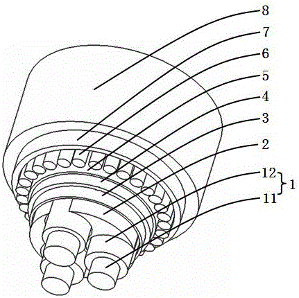
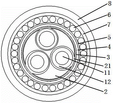
[0034] please see figure 1 and figure 2 , separate lightning protection cable, including three electric units 1, inner sheath 4, armor layer 7, outer sheath 8, and grounding layer 6, the electric unit is composed of a conductor 11 and an insulating layer 12 covering the conductor; the inner The sheath is extruded and coated on the outside of the first protective layer 3, the inner sheath is covered with a second protective layer 5, the grounding layer is located outside the second protective layer, the armored layer is coated on the outside of the grounding layer, and the outer sheath The sleeve is extruded and coated outside the armor layer; the armor layer is a single-sided coated steel tape, and the surface of the armor layer in contact with the ground layer is the non-coated surface; the first protective layer and the second protective layer are both mica Belt; it is characterized in that there is an integrated position fixing element 2 in the first protective layer, and...

Embodiment 2

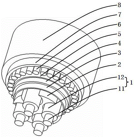
[0036] please see image 3 and Figure 4 , and refer to figure 1 and figure 2 , a separate lightning protection cable, including four electrical units 1, an inner sheath 4, an armor layer 7, an outer sheath 8, and a grounding layer 6. The electrical unit is composed of a conductor 11 and an insulating layer 12 covering the conductor; The inner sheath is extruded and coated on the outside of the first protective layer 3, the inner sheath is covered with the second protective layer 5, the grounding layer is located outside the second protective layer, the armored layer is coated on the outside of the grounding layer, and the outer The sheath is extruded and coated outside the armor layer; the armor layer is a single-sided coated steel tape, and the surface of the armor layer in contact with the ground layer is the non-coated surface; the first protective layer and the second protective layer are both Mica tape; it is characterized in that there is an integrated position fixi...

Embodiment 3

[0038] please see Figure 5 and Figure 6 , and refer to Figure 1 to Figure 4 , The separate lightning protection cable is basically the same as the implementation example 2, except that there is a reinforcing member 9 in the center of the position fixing element.

[0039] Of course, the separate lightning protection cable described in any of the above implementation examples is characterized in that there can be other multiple electric units, and there can be other multiple receiving holes, and the number of electric units is not greater than the number of receiving holes. When the number of electrical units is less than that of the accommodation holes, some of the accommodation holes are empty, and other communication or power transmission media can be placed or reserved.

[0040] The separate lightning protection cable described in any of the above implementation examples is characterized in that the central axes of the plurality of receiving holes are on the same cylind...


PUM

PropertyMeasurementUnit
lengthaaaaaaaaaa
thicknessaaaaaaaaaa

Abstract

The invention belongs to the technical field of cables, and particularly relates to a separation-type lightning protection cable. The separation-type lightning protection cable comprises electric units, an inner jacket, an armoring layer, an outer jacket and a grounding layer; the inner jacket sleeves outside a first protective layer, a second protective layer is arranged outside the inner jacket, the grounding layer is arranged outside the second protective layer, the armoring layer is arranged outside the grounding layer, and the outer jacket is arranged outside the armoring layer; the first / second protective layer is made of a mica tape; and the separation-type lightning protection cable is characterized in that a position fixing element is arranged in the first protective layer, the position fixing element has a plurality of storage holes which are not communicated with each other, the electric units are distributed in the storage holes, and each storage hole is only provided with one electric unit; each storage hole is provided with an opening which is arranged on the edge of the position fixing element, and the electric unit can stretch into the storage hole or be taken out from the storage hole through the opening; besides the opening position, the edge of the position fixing element is positioned on the same cylindrical surface. The separation-type lightning protection cable has the beneficial effects that simplicity in production is realized, the production speed is high, the resistance rate of the grounding layer is low and the maintenance cost is low; the electric power still can be normally transmitted when the cable is provided with high load or struck by the lightning.

Description

technical field [0001] The invention belongs to the technical field of cables, in particular to separate lightning protection cables. Background technique [0002] At home and abroad, the cables used for communication base stations are mainly considered to be flame-retardant, fire-resistant, and flexible. They have not considered that the lightning caused by the cable will damage the communication equipment or damage the cable itself, resulting in power interruption of the communication network and paralyzing the communication network. The power system of the communication base station is generally a low-voltage system. For the lightning protection of the low-voltage system, in addition to the direct lightning strike, the most destructive effect is the secondary effect. The lightning produces electrostatic field, alternating electromagnetic field and electromagnetic radiation, and the lightning electromagnetic pulse LEMP is formed by lightning wave intrusion and ground poten...

Claims


Application Information

Patent Timeline
Patent Type & Authority Patents(China)
IPC IPC(8): H01B7/02H01B7/29H01B3/44H01B7/17
Inventor 王国梁李念东于国昌王亚鹏张凤芝韩慧卉苗涛
Owner ZHANGQIU POWER SUPPLY CO OF STATE GRID SHANDONG ELECTRIC POWER CO
Why Eureka
Try Eureka