An airflow spreading device

An air flow and side plate technology, applied in textiles, papermaking, filament generation, etc., can solve the problems of discontinuous fiber spreading process, decreased fiber spreading quality, prone to turbulent components, etc., and achieves simple and compact structure, small volume, The effect of less air turbulence components

Active Publication Date: 2017-03-29
WEIHAI BAOWEI NEW MATERIAL TECH CO LTD
View PDF7 Cites 0 Cited by
  • Summary
  • Abstract
  • Description
  • Claims
  • Application Information

AI Technical Summary

Problems solved by technology

[0003] Compared with other fiber spreading technologies, while the airflow fiber spreading technology has great advantages, there are also many key technologies to be overcome. For example, turbulent flow components are prone to occur during the fiber spreading process, which will cause changes in the fiber path and cause a decline in the quality of the fiber development. ; It is difficult to control the uniformity of fiber spreading, and the structural design of the fiber spreading device needs to be improved
In the disclosed air-flow fiber spreading technology, the air-flow fiber spreading device is often designed as a square or circular suction wind tunnel tube, such as the fiber spreading device used in patent CN1173083C and CN102439206, which is easy to cause turbulent flow, and The structure of the device is often not adjustable, and it is prone to discontinuity in the fiber spreading process, so it is not suitable for the fiber spreading work of various specifications of carbon fibers

Method used


Image

  • An airflow spreading device
  • An airflow spreading device
  • An airflow spreading device

Examples


Embodiment Construction

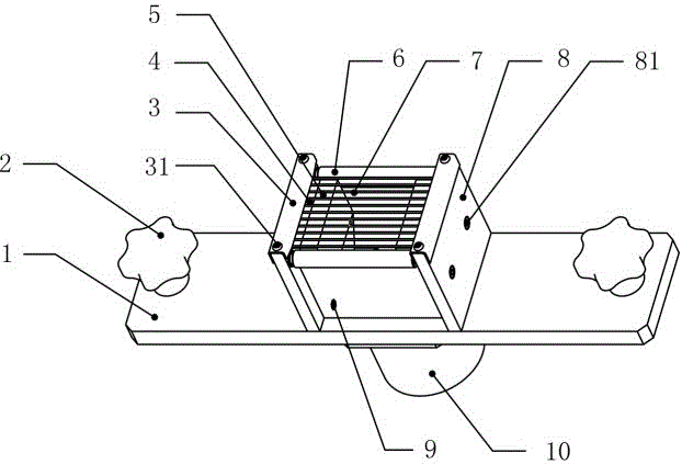
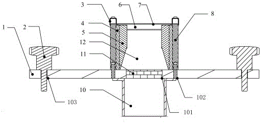
[0019] From figure 1 It can be seen from the figure that an airflow spreading device includes a base plate 1, a supporting side plate 8, a sheet metal vertical plate 9, a wedge-shaped side plate 5, a guide rod 6, a supporting rod 7, a pressure plate 3, a ventilation pipe 10 and a rectifying net 11 Wait. The central position of the base plate 1 is provided with a suction tuyere and is connected with the ventilation pipe 10. The suction tuyere has a built-in rectifying net 11. Two supporting side plates 8 are respectively fixed on the left and right sides of the suction tuyere of the base plate 1. The front and rear sheet metal vertical plates 9 are respectively clamped Insert the strip-shaped slot 82 of the supporting side plate, the base plate 1, the supporting side plate 8 and the sheet metal vertical plate 9 enclose a cavity 12; the wedge-shaped side plate 5 is symmetrically fixed on the inner side of the supporting side plate 8 by screws, forming an upper Narrow and wide u...


PUM


Abstract

The invention relates to an air-flow fiber spreading device. The device comprises a base plate, support side plates, vertical metal plates, side wedge-shaped plates, guide rods, support rods, pressing plates, a vent pipe and a rectification net, and the side wedge-shaped plates are symmetrically fixed to the inner sides of the support side plates, so that an equal-section cavity with the upper end narrow and the lower end wide is formed; the multiple support rods are arranged on the side wedge-shaped plates in a pressed mode, and the two ends of each rod are fixed to a left support side plate and a right support side plate through the pressing plates respectively; the guide rods are located on the upper portion of a front vertical metal plate and the upper portion of a rear vertical metal plate and installed on the left support side plate and the right support side plate. Air flow flows through the interior of the cavity from top to bottom in a laminar-flow state, and the fibers are bent in a bow shape under the action of the attraction air flow, so that filaments are loosened and spread in the width direction. According to the air-flow fiber spreading device, the structure is simple and compact, the size is small, turbulence constituents in the air flow inside the cavity are few, the opening width can be adjusted according to fiber expanding requirements, the air flow is utilized for widening and thinning the carbon fibers, carbon fiber sheets which are uniform in width are obtained, and the device is an ideal air-flow fiber spreading device.

Description

technical field [0001] The invention relates to a fiber spreading processing machine for composite materials, in particular to an airflow spreading device for carbon fiber tow. Background technique [0002] In recent years, fiber reinforced composite materials have been widely used. In order to increase the contact area between the fiber filament and the matrix and increase the mechanical properties of the material, it is necessary to widen and thin the fiber filament bundle to obtain a high-quality material with a small mass per unit area and small deviations in physical properties. The existing carbon fiber spreading device is mainly based on mechanical rolling, and there are also fiber spreading methods such as ultrasonic vibration, mechanical vibration, and electrostatic fiber spreading. The above technologies cause great damage to the tow through strong fiber spreading, and at the same time, the spreading width and uniformity cannot be guaranteed. The air-flow fiber s...

Claims


Application Information

Patent Timeline
Patent Type & Authority Patents(China)
IPC IPC(8): D01D11/02
CPCD02J1/18
Inventor 黄博姜波钟鸣苑寿同
Owner WEIHAI BAOWEI NEW MATERIAL TECH CO LTD
Why Eureka
Try Eureka