Method and product for greatly changing rigidity of conical spring

A conical spring and variable stiffness technology, applied in the direction of springs, can solve problems such as difficulty in satisfying multiple stiffness changes of locomotives, wrinkles and cracks of rubber body, and achieve the effect of preventing locomotive derailment, preventing cracking, and increasing comfort

Active Publication Date: 2015-08-26
ZHUZHOU TIMES RUIWEI ANTI VIBERATION EQUIP LTD
View PDF8 Cites 3 Cited by
  • Summary
  • Abstract
  • Description
  • Claims
  • Application Information

AI Technical Summary

Problems solved by technology

However, this utility model patent does not allow the axlebox spring to achieve multiple variable stiffness structures, which is difficult to meet the multiple stiffness changes required by the locomotive in different states
[0008]Therefore, so far, there is no effective way to prevent the rubber body from wrinkling and cracking when the conical spring changes its stiffness, and it can meet the multiple times required by the locomotive in different states. The method and device of stiffness change, so it is necessary to further improve this

Method used


Image

  • Method and product for greatly changing rigidity of conical spring
  • Method and product for greatly changing rigidity of conical spring
  • Method and product for greatly changing rigidity of conical spring

Examples


Embodiment 1

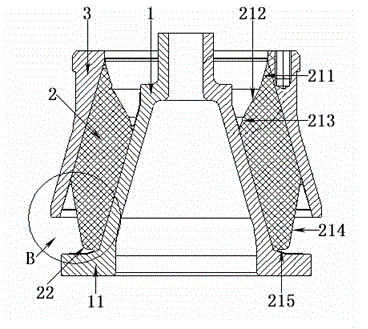
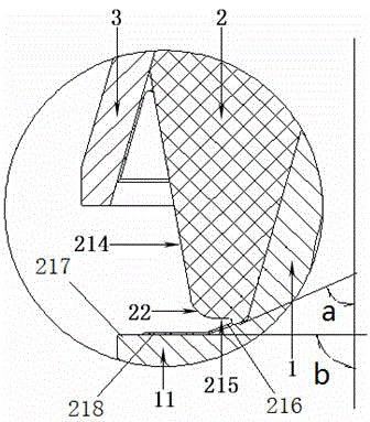
[0041] like figure 1 with figure 2 As shown, the conical spring includes an inner cone 1 , a rubber body 2 and an outer cone 3 , and the lower end of the inner cone 1 extends outward to form an annular inner cone boss 11 . The upper end surface 21 of the rubber body 2 is a three-segment multi-segment downhill structure, which are respectively the first circular straight segment 211, the second circular straight segment 212 and the third circular straight segment 213. The circular fillet section 22 is used for transition. The lower end surface of the rubber body 2 is a two-stage multi-stage uphill structure, which are respectively the fourth annular straight section 214 and the fifth annular straight section 215, between the fourth annular straight section 214 and the fifth annular straight section 215 Also adopt the circular fillet segment 22 transition. In this embodiment, the fillet radius of the annular fillet section 22 at the lower end of the rubber body 2 is 20 ...

Embodiment 2

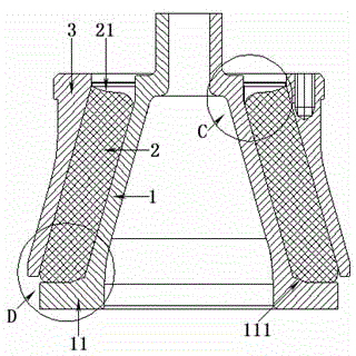
[0047] The structure is roughly the same as that of Embodiment 1, but the upper end surface of the inner cone boss 11 is not a gentle straight line transition, but a gentle curve edge transition, and the upper end surface of the inner cone boss 11 adopts a three-section annular flat Straight section and two sections of annular fillet section, which can further change the number of times of variable stiffness of the variable conical spring, increase or decrease the number of sections of the annular straight section can further improve the smoothness of the maximum vertical load process, and ensure the rubber body 2 Wrinkles do not appear in the shape of the lower end, and the shape can always be kept smooth. Simultaneously, in order to avoid cracking at the lower end of the rubber body 2, the upper end surface of the upper end surface of the inner cone boss 11 is also covered with a layer of rubber layer 218 (see attached figure 2 ), the rubber layer is integrated with the l...


PUM


Abstract

The invention discloses a method and a product for greatly changing rigidity of a conical spring. The product comprises an inner cone, a rubber body and an outer cone, wherein the rubber body surrounds the inner cone; the outer cone surrounds the rubber body; the rubber body, the inner cone and the outer cone form a conical rubber metal spring together; the lower end surface of the rubber body is respectively connected with the inner cone and the outer cone of the conical spring; the rubber body is in the trend of gradually rising from the part being connected with the inner cone to the part being connected with the outer cone. The product is characterized in that a boss protrudes outwards from the bottom of the inner cone, and after the rubber body moves down until the lower end surface of the rubber body is propped against the boss, the boss protruding outwards from the bottom of the inner cone and the inner side of the outer cone are in double restraint coordination to generate great variable rigidity. Through the change of the shape, the slope and the length of each section of the boss as well as the number of sections, the rigidity change magnitude and the rigidity change position of the conical spring are adjusted, and the adjustment of repeatedly changing the rigidity is realized through the control of the number of sections.

Description

technical field [0001] The invention relates to the improvement of conical springs on locomotives, in particular to a method for adjusting the stiffness of the conical springs and a conical spring structure. Shaped spring rubber cracks due to wrinkling when compressed with use. It belongs to the technical field of elastic damping. Background technique [0002] The conical spring is also called the axle box spring, which mainly refers to the spring with damping effect combined with metal and rubber on the locomotive. The conical spring is installed between the axle box and the frame of the rail locomotive to support, dampen and reduce noise. It is a commonly used rubber-metal composite vibration- and noise-reducing element. On the car body, the main function is to bear the load of the car body and frame. The tapered metal parts and the rubber are vulcanized into a whole under a certain temperature and pressure through the adhesive. Its function is to use the vulcanized rub...

Claims


Application Information

Patent Timeline
Patent Type & Authority Applications(China)
IPC IPC(8): F16F1/393
CPCF16F1/393
Inventor 谭方丁纬孙海燕冯万盛柳禄泱
Owner ZHUZHOU TIMES RUIWEI ANTI VIBERATION EQUIP LTD
Why Eureka
Try Eureka