Manual speed-adjustment permanent-magnet coupler
A technology of permanent magnet coupler and manual speed regulation, applied in the field of couplers, can solve the problems of low efficiency, high cost, complicated structure of adjustment device, etc.
- Summary
- Abstract
- Description
- Claims
- Application Information
AI Technical Summary
Problems solved by technology
Method used
Image

Examples
Embodiment 1
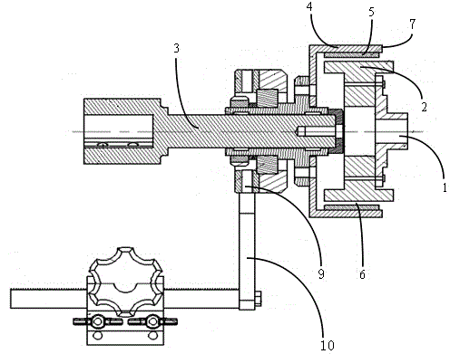
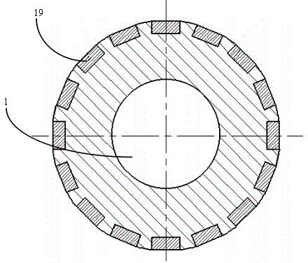
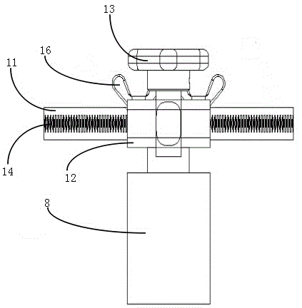
[0021] Such as figure 1 , figure 2 and image 3 As shown, a permanent magnet coupler with manual speed adjustment includes a permanent magnet coupler, the permanent magnet coupler includes a power part and a transmission part, and the power part includes a motor (not shown), and a motor shaft 1 Connected conductor column 2, the transmission part includes a transmission shaft 3, a magnet cylinder 4 arranged on the transmission shaft 3 that can rotate synchronously with the transmission shaft 3, and two permanent magnets 5 disposed inside the magnet cylinder 4, the conductor There is an air gap 6 between the column 2 and the permanent magnet 5, and the distance between the adjacent permanent magnets along the circumference of the magnet cylinder is the same, and the permanent magnet 5 arranged on the magnet cylinder 4 does not exceed its corresponding outer edge 7, and It includes a speed regulating device arranged in the transmission part of the permanent magnetic coupler. ...
Embodiment 2
[0024] Such as figure 1 , figure 2 and image 3 As shown, a permanent magnet coupler with manual speed adjustment includes a permanent magnet coupler, the permanent magnet coupler includes a power part and a transmission part, and the power part includes a motor (not shown), and a motor shaft 1 Connected conductor column 2, the transmission part includes a transmission shaft 3, a magnet cylinder 4 arranged on the transmission shaft 3 that can rotate synchronously with the transmission shaft 3, and three permanent magnets 5 disposed inside the magnet cylinder 4, the conductor There is an air gap 6 between the column 2 and the permanent magnet 5, and the distance between the adjacent permanent magnets along the circumference of the magnet cylinder is the same, and the permanent magnet 5 arranged on the magnet cylinder 4 does not exceed its corresponding outer edge 7, and It includes a speed regulating device arranged in the transmission part of the permanent magnetic coupler....
PUM
 Abstract
Description
Claims
Application Information
 - R&D
- Intellectual Property
- Life Sciences
- Materials
- Tech Scout
- Unparalleled Data Quality
- Higher Quality Content
- 60% Fewer Hallucinations
Browse by: Latest US Patents, China's latest patents, Technical Efficacy Thesaurus, Application Domain, Technology Topic, Popular Technical Reports.
© 2025 PatSnap. All rights reserved.Legal|Privacy policy|Modern Slavery Act Transparency Statement|Sitemap|About US| Contact US: help@patsnap.com