Forming and driving method for triggering type permanent magnet brushless direct-current motor

A DC motor and permanent magnet brushless technology, applied in the field of DC motors and electric motors, achieves the effects of cost saving, simple driving circuit and easy material acquisition

Active Publication Date: 2015-02-25
朱福善
View PDF9 Cites 5 Cited by
  • Summary
  • Abstract
  • Description
  • Claims
  • Application Information

AI Technical Summary

Problems solved by technology

[0009] In order to solve the problem that the brushed DC motor must run with brushes in the prior art

Method used


Image

  • Forming and driving method for triggering type permanent magnet brushless direct-current motor
  • Forming and driving method for triggering type permanent magnet brushless direct-current motor
  • Forming and driving method for triggering type permanent magnet brushless direct-current motor

Examples


Embodiment Construction

[0074] The following describes in detail with reference to the best embodiment shown in the accompanying drawings.

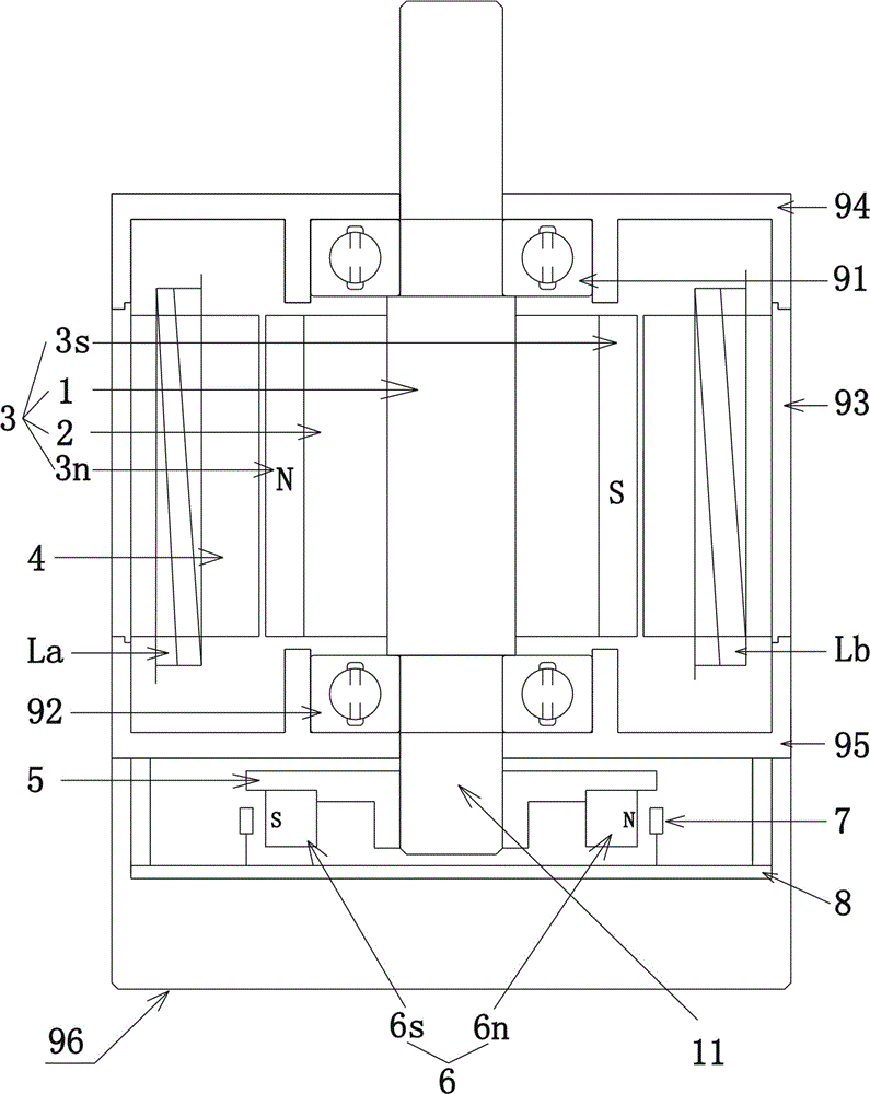
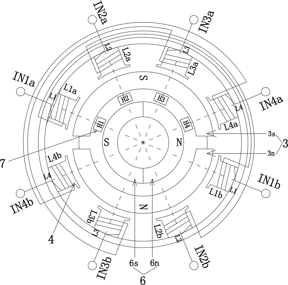
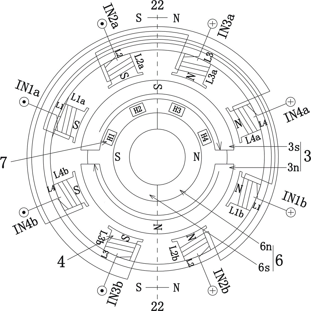
[0075] Such as figure 1 -- Figure 6 As shown, a trigger type permanent magnet brushless DC motor is designed and manufactured, and the motor includes:

[0076] The rotor core 2 is set on the rotor shaft 1, and the permanent magnets 3n and 3s are fixed on the rotor core 2 to form the magnetic poles of the permanent magnet rotor 3. The permanent magnets 3n and 3s are prefabricated by magnetic materials and magnetized. The magnetic tile; the permanent magnet rotor 3 has two poles or four poles.

[0077] A stator is provided with a plurality of stator pole cores 4, and the stator pole cores 4 are arranged in an even number; pole core coils are wound on the stator pole cores, and two coils winding to the same pole core coils are connected in series to form a phase winding L.

[0078] In a two-pole motor, the stator armature winding consists of at least two phase wi...


PUM


Abstract

The invention discloses a forming and driving method for a triggering type permanent magnet brushless direct-current motor. The forming and driving method includes the steps that a rotor and a triggering magnetic ring are arranged, wherein the triggering magnetic ring rotates along with the rotor and is the same as the rotor in pole number, and the same poles of the triggering magnetic ring and the rotor are staggered; coils are wound around stator pole shanks, and the coils on the stator pole shanks are connected in series to form phase windings; basic control units with the phase as the unit are composed of sensors, H bridges and the phase windings, and a driving circuit of the motor is composed of the multiple basic control units; the sensors of the basic control units are triggered by the triggering magnetic ring to output position signals of the rotor magnetic poles to control the output states of the H bridges, currents of the phase windings are connected, the directions of the currents in all phases are controlled, a stator magnetic field which is the same as the triggering magnetic ring in pole number and space distribution is triggered by the currents in the phases, and the rotor is driven to rotate. Compared with the prior art, by means of the method, the defects of a traditional direct-current motor are overcome, the advantages of the traditional direct-current motor are kept, and the forming and driving method has the advantages that the speed can be adjusted, position-negative rotation control is convenient, and the driving circuit is simple.

Description

technical field [0001] The invention relates to a motor, in particular to a direct current motor, especially a permanent magnet brushless direct current motor with electromechanical integration. Background technique [0002] In the prior art, the DC motor has been inseparable from the commutator and brushes since its appearance. When the brush is in contact with the high-speed rotary commutator, electric sparks will be generated. The electric spark will not only cause electromagnetic interference to the surrounding electronic equipment, but also accelerate the wear of the brushes and commutator. Coupled with inherent shortcomings such as speed regulation and difficulty in forward and reverse control, it limits its application in modern CNC servo systems. [0003] At present, there are two types of small and medium power motors used in the field of numerical control, also known as permanent magnet brushless motors: [0004] 1. Three-phase square wave permanent magnet brushl...

Claims


Application Information

Patent Timeline
Patent Type & Authority Applications(China)
IPC IPC(8): H02K29/00H02K29/06H02K1/27H02K3/28H02K15/00H02P6/08H02P6/22
CPCH02K1/2753H02K3/28H02K29/00H02K29/06H02P6/085H02P6/22
Inventor 朱福善
Owner 朱福善
Why Eureka
Try Eureka