
Pupil distance measurement device and method

A technology of measuring device and measuring method, which is applied in the field of optometry, can solve problems such as inability to measure, and achieve the effect of avoiding subjective errors and high efficiency

Inactive Publication Date: 2015-09-02
张仕郎
View PDF6 Cites 3 Cited by
  • Summary
  • Abstract
  • Description
  • Claims
  • Application Information

AI Technical Summary

Problems solved by technology

[0012] 3. The optometrist must be on site to measure, and it cannot be measured without being on site

Method used


Image

  • Pupil distance measurement device and method

Examples


Embodiment Construction

[0027] Embodiments of the present invention will be further described below in conjunction with the accompanying drawings.

[0028] In order to make the purpose, technical solution and advantages of the present invention clearer, the present invention will be further described in detail below in combination with functional diagrams and flow charts. The following exemplary embodiments and their descriptions are used to explain the present invention, but are not intended to limit the present invention.

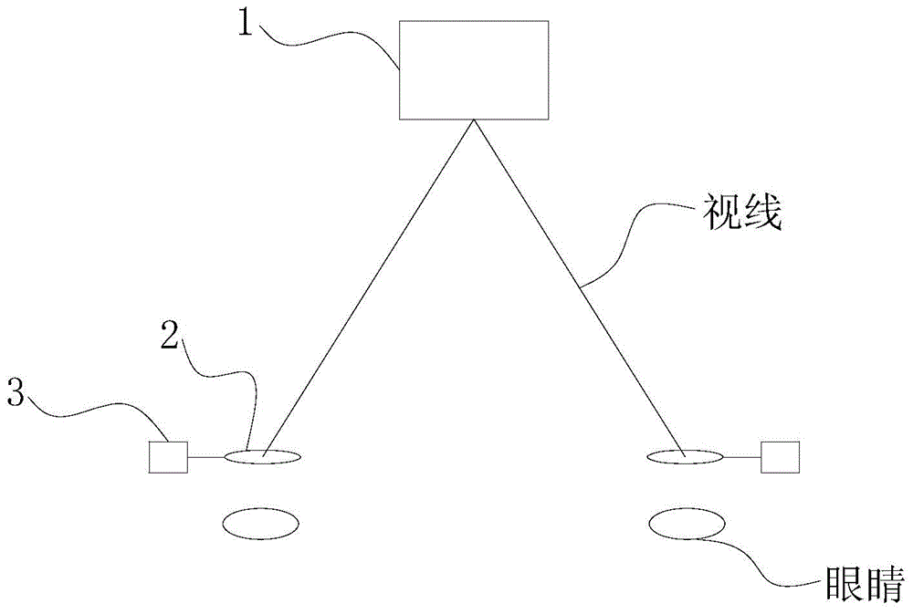
[0029] See figure 1 Shown, a kind of interpupillary distance measuring device is characterized in that: comprise object 1, pinhole sheet 2 and driver 3; Said driver 3 drives described pinhole sheet 2 to move in horizontal direction; Described pinhole sheet 2 shares 2 tablets. The driver 3 is driven by remote control.

[0030] A method for interpupillary distance measurement, characterized in that: comprising the following steps:

[0031] Step 1, adjust the two pinhole sheets...


PUM


Abstract

The invention discloses a pupil distance measurement device which comprises a target object, two needle hole pieces and a driver. The driver drives the needle hole pieces to move in the horizontal direction. The pupil distance measurement device can accurately measure a pupil distance and can remotely control measurement, and the pupil distance can be measured even if an optometrist is not in a site.

Description

technical field [0001] The invention relates to the field of optometry, in particular to a device and method for measuring interpupillary distance. Background technique [0002] Existing pupillary distance measurements include the following steps: [0003] (1) The examiner and the patient are facing each other with a distance of 40cm, so that the eyes of the two are kept at the same height. [0004] (2) The examiner holds the pupillary ruler or ruler with the right thumb and index finger, rests the other fingers against the patient's cheek, and then places the pupillary ruler at the lowest point of the bridge of the nose, and tilts slightly along the angle of the bridge of the nose. [0005] (3) The examiner closes the right eye, and makes the patient's right eye look at the examiner's left eye. When the left eye is looking at the patient's right eye, the examiner aligns the "zero position" of the pupillary distance ruler with the pupil center of the patient's right eye. ...

Claims


Application Information

Patent Timeline
IPC IPC(8): A61B3/11
Inventor 张仕郎
Owner 张仕郎
Learn More