Supercharge Your Innovation With Domain-Expert AI Agents!

Barn feed device

A technology for a barn and a hoist, which is applied to the field of barn feeding devices, can solve the problems that the feeding device cannot be used together, cannot separate grain impurities, and does not have the function of removing impurities.

Active Publication Date: 2015-09-02
SHANDONG REALIFE DRYING MACHINERY TECH CO LTD
View PDF13 Cites 0 Cited by
  • Summary
  • Abstract
  • Description
  • Claims
  • Application Information

AI Technical Summary

Problems solved by technology

Such a feeding device does not have the function of removing impurities and cannot separate the impurities in the grain
Most of the existing grain removal devices use wind to remove lighter chaff and weeds, and use magnets to absorb iron impurities, which cannot be used in conjunction with the feeding device

Method used


Image

  • Barn feed device
  • Barn feed device
  • Barn feed device

Examples


Embodiment Construction

[0013] The present invention will be further described below in conjunction with the accompanying drawings and specific embodiments.

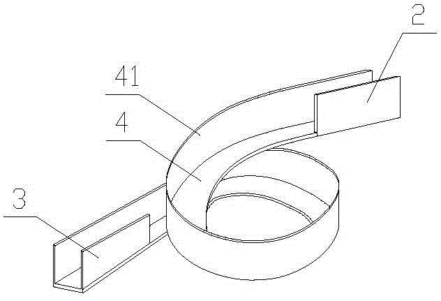
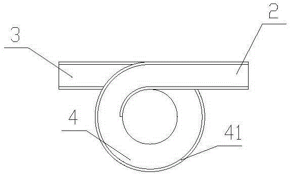
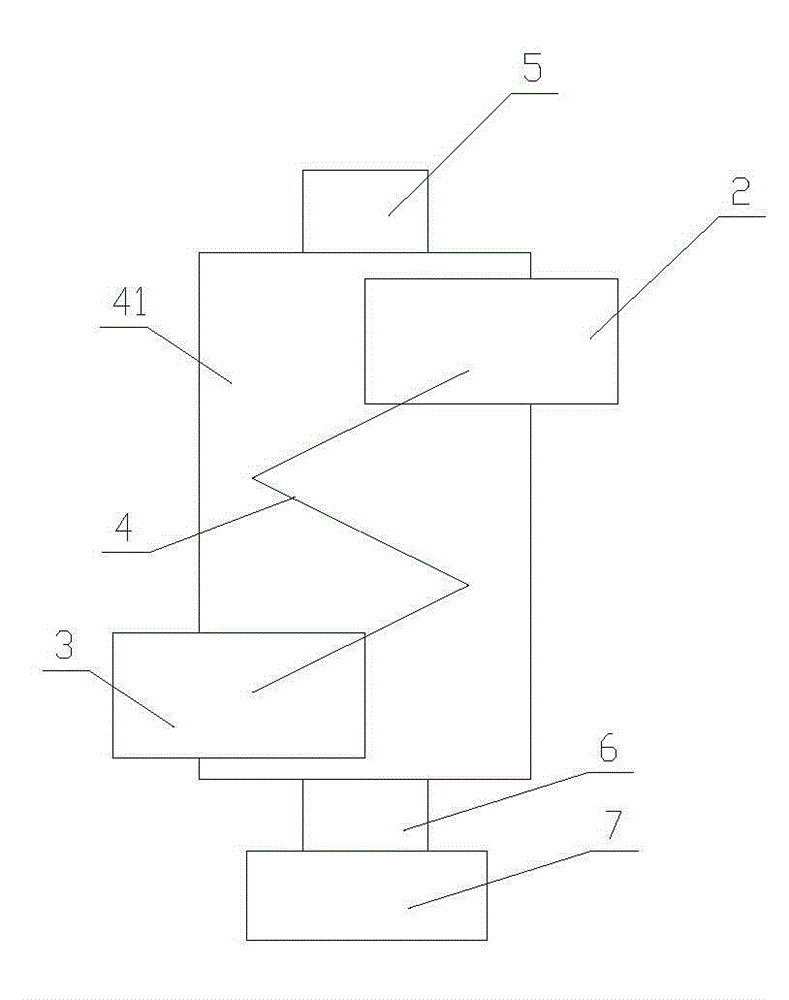
[0014] like figure 1 , figure 2 As shown, the barn feeding device of the present invention includes a hoist, a conveying channel located at the upper end of the hoist to communicate with the output end of the hoist and the barn, and the conveying channel includes an inlet communication section 2 connected to the output end of the hoist, connected to the The outlet communicating section 3 at the upper end of the barn, the spiral descending section 4 located between the inlet communicating section 2 and the outlet communicating section 3, the spiral descending section 4 is a spiral slide that gradually decreases in height from the entrance to the exit, and the spiral descending section The entrance of 4 communicates with the inlet communication section 2, the outlet communicates with the outlet communication section 3, and the outer wall of the...


PUM


Abstract

The invention relates to a machinery for processing and storing grains, and specifically relates to a barn feed device. The barn feed device comprises a hoister, a conveying channel located at the upper end of the hoister and communicated with an output end of the hoister and a barn. The conveying channel comprises an inlet communicating section connected with the output end of the hoister, an outlet communicating section connected with the upper end of the barn, and a spiral descending section located between the inlet communicating section and the outlet communicating section. The spiral descending section is a spiral sliding chute with its height reducing gradually from the inlet to the outlet. The inlet of the spiral descending section is communicated with the inlet communicating section, and the outlet thereof is communicated with the outlet communicating section. An external wall of the spiral sliding chute forming the spiral descending section is fixedly connected with an external baffle plate; and the internal side of the spiral sliding chute is suspended. Being compact in structure and capable of removing the impurities while conveying the grains, the barn feed device uses the principle that different grains and impurities have different centrifugal forces to separate the impurities in the grains, thereby saving the production cost and reducing the energy consumption.

Description

technical field [0001] The invention relates to a machine for grain processing and storage, in particular to a barn feeding device. Background technique [0002] Existing barn feeding device utilizes auger or lifter to lift the grain to a high place, and then guides the grain into the barn through the pipeline inclined at the upper end of the auger or lifter. Such feeding device does not have the impurity removal function, and cannot separate the impurities in the grain. Existing grain impurity removal devices mostly use wind to remove lighter chaff and weeds, and utilize magnets to absorb iron impurities, which cannot be used in conjunction with the feeding device. Contents of the invention [0003] The object of the present invention is to provide a barn feeding device with compact structure, capable of removing impurities while transporting grains. [0004] To achieve the above object, the present invention adopts the following technical solutions: [0005] The barn ...

Claims


Application Information

Patent Timeline
Patent Type & Authority Applications(China)
IPC IPC(8): B65G69/00
CPCB65G69/20
Inventor 王炳福孙守民冀民民徐峰王金玉
Owner SHANDONG REALIFE DRYING MACHINERY TECH CO LTD
Features
  • R&D
  • Intellectual Property
  • Life Sciences
  • Materials
  • Tech Scout
  • Unparalleled Data Quality
  • Higher Quality Content
  • 60% Fewer Hallucinations
Learn More