
touch faucet

A faucet and faucet technology, applied in the faucet field, can solve the problems of agility and convenience, unfavorable installation, limited use space, etc.

Active Publication Date: 2017-06-30
GLOBE UNION INDAL
View PDF6 Cites 2 Cited by
  • Summary
  • Abstract
  • Description
  • Claims
  • Application Information

AI Technical Summary

Problems solved by technology

[0005] Although the above-mentioned water saving valve has the advantages of convenient installation and operation, water saving and simple structure, it is also the biggest disadvantage that the user must directly touch the actuating component of the water saving valve, because when the user touches the actuating component , which also means that the dirt on the hands is simultaneously contaminated on the actuating component. From the above patent technical documents and existing products, it can be clearly found that the water flowing through the economizer usually flushes and flows through the actuating component, so that The dirt on it is washed away with the water flow, so that the water is polluted
Therefore, these water-saving valves cannot pass the relevant laws and regulations on water sanitation in some countries and regions, and are prohibited from being used in specific water environments.
[0006] The switch water of the traditional faucet is controlled by one handle and one mandrel to control the water outlet, or to adjust and control the outlet water temperature, but the operation control method of turning the mandrel by the handle will affect the agility and convenience of operation due to the large actuation stroke.
In addition, its operating space is large, if it is too close to the wall or the space is narrow, it is not conducive to installation
Items are usually not placed within the operating range of the handle, so the usable space is greatly limited
The control structure of the handle and the mandrel will also affect the beauty and texture of the exterior design, which is not conducive to enhancing the added value of the product

Method used


Image

  • touch faucet
  • touch faucet
  • touch faucet

Examples


no. 1 example

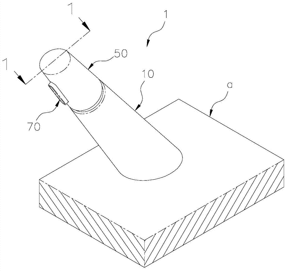
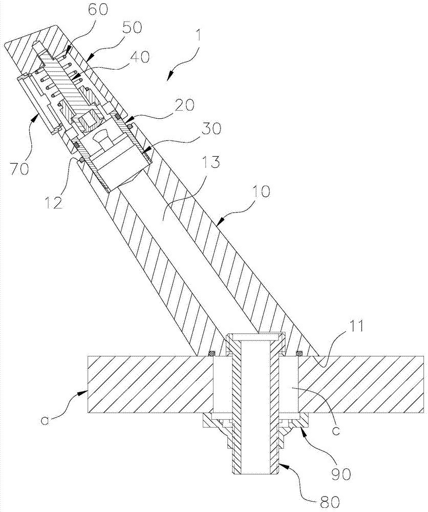
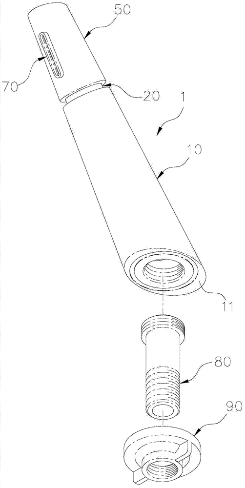
[0094] Such as Figures 1 to 3 As shown, the present invention provides a first embodiment of a touch-control faucet. The touch-control faucet 1 can be installed on a fixed wall a, and mainly includes a faucet body 10, a positioning socket 20, a province Water valve 30, an actuating rod 40 and a pressing cover 50; wherein:

[0095] Such as Figure 4 As shown, the faucet body 10 has a water inlet 11 , a water outlet 12 , and a water flow channel 13 between the water inlet 11 and the water outlet 12 .

[0096] Such as Figures 5 to 8 As shown, the positioning socket 20 is fixedly connected to the water outlet end 12 of the faucet body 10 , and at least one water hole 21 and one through hole 22 are disposed on it. In this embodiment, four water passage holes 21 are equiangularly arranged along the circumferential direction.

[0097] The water-saving valve 30 is arranged between the water outlet 12 of the faucet body 10 and the positioning cylinder seat 20, and an operating va...


PUM


Abstract

The invention provides a touch control type tap. A touch control type water-saving valve is installed in a tap which is provided with a temperature adjustment function or is not provided with a temperature adjustment function, a pressing cover or pressing button which can be operated by a user in a touch manner is arranged to indirectly touch the water-saving valve, the tap is provided with a touch control type water switching function, a traditional mandrel operation mode can be effectively replaced, and a water saving effect can be reached. More importantly, the user can be prevented from directly touching the water-saving valve by a hand, and when passing through the water-saving valve, the water current is not polluted, and sanitary requirements and correlated national legislation demands can be satisfied. Furthermore, the water discharging direction can be changed, and compared with a common water-saving valve installed on the water outlet of the tap, the touch control type water-saving valve can achieve different water discharging types and jet flow types.

Description

technical field [0001] The invention relates to a faucet, in particular to a touch faucet which switches water by pressing and touching. Background technique [0002] Due to many disadvantages of high cost, complex structure, and high failure rate, the early infrared sensor water saving valves have been developed successively, and have been disclosed in many patent technical documents. For example, the non-self-closing water saving valves disclosed in Taiwan certificate numbers M432670 and I228578, and the self-closing water saving valves disclosed in Taiwan certificate numbers I369459, M452280 and M382408. The common feature of the water saving valves is that they can be installed at the water outlet of the faucet, and they all have rod-shaped actuating components that protrude from the bottom of the water saving valve and can be moved upward by the user. In the open state, as long as the user touches the actuating component upwards, the water-saving valve can be opened, s...

Claims


Application Information

Patent Timeline
Patent Type & Authority Patents(China)
IPC IPC(8): F16K31/60F16K31/64
CPCF16K31/60G05D23/00
Inventor 林颐苹李俊宏袁家骅吴柏贤陈琬珊
Owner GLOBE UNION INDAL
Learn More