Steam generator improvement structure

A steam generator and heating element technology, applied in steam generation, steam generation methods, steam boilers, etc., can solve problems such as soft hoses, abnormal water supply, sagging and folding of hoses, etc.

Inactive Publication Date: 2015-09-02
广东佳明电器有限公司
View PDF6 Cites 1 Cited by
  • Summary
  • Abstract
  • Description
  • Claims
  • Application Information

AI Technical Summary

Problems solved by technology

When the hose is supplying water downwards, there will be no problem. However, depending on the usage conditions, when it is necessary to supply water upwards, the hose will become soft under the action of gravity due to the high temperature in the steam generator. The water supply channel is closed by drooping and folding, so that the water cannot be supplied normally

Method used


Image

  • Steam generator improvement structure
  • Steam generator improvement structure

Examples


Embodiment 1

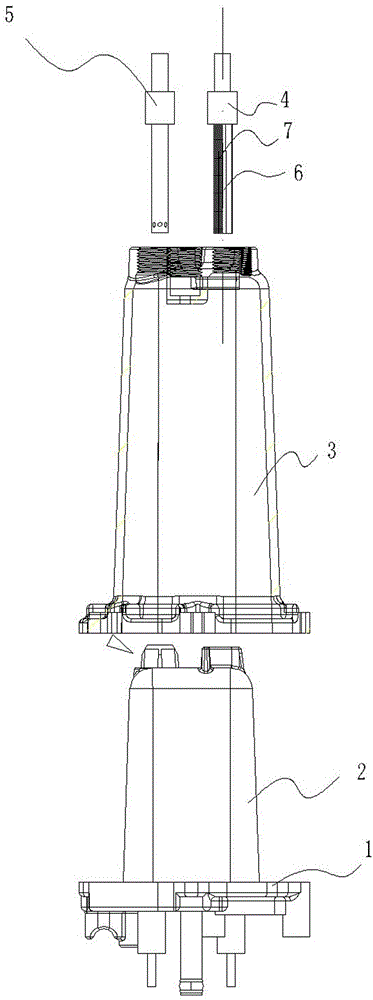
[0010] Embodiment 1: as figure 1 As shown, the present invention includes a columnar heating element 2 with a fixed base plate 1, a casing 3 that is sleeved on the outside of the columnar heating element 2 and fixed on the fixed base plate 1, and the columnar heating element 2 includes a heating wire, and the outer casing 3 that is cast on the heating wire Heat conductor (aluminum), the top of the casing 3 is provided with a water inlet member 4 and a steam outlet member 5, and a hose 6 connected to the water inlet member 4 is arranged inside the casing 3, and the special feature is that the hose 6 is sleeved There is a cylindrical metal net 7 , and one end of the cylindrical metal net 7 is fixed to the water introduction member 4 .

Embodiment 2

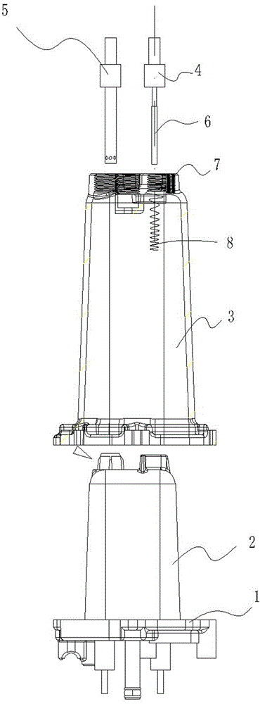
[0011] Embodiment 2: as figure 2 As shown, in this embodiment, on the basis of Embodiment 1, a cylindrical spring ring 8 is used to replace the cylindrical metal mesh 7 , and one end of the cylindrical spring ring 8 is fixed on the inner wall of the top of the housing 3 .


PUM


Abstract

A steam generator improvement structure comprises a columnar heating element provided with a fixing bottom plate and a shell sleeving the columnar heating element from the outer side and fixed on the fixing bottom plate. A water lead-in component and a steak lead-in component are arranged at the top of the shell, and a hose connected on the water lead-in component is arranged in the shell. The steam generator improvement structure is characterized in that the hose is sleeved with a tubular metal net or a tubular spring ring, and one end of one of the tubular metal net or the tubular spring ring is fixed on the water lead-in component or the inner side wall of the top of the shell. Compared with the prior art, the steam generator improvement structure has the advantage that the hose can supply water in any state.

Description

Technical field: [0001] The invention relates to a steam production device. Background technique: [0002] The steam generator used on the existing floor mop is generally composed of a columnar heating element with a fixed bottom plate, a shell that is sleeved on the columnar heating body and fixed on the fixed bottom plate. hose. Water is injected from the gap between the heating element on the bottom surface and the shell through the downward hose, and the steam is exported from the top of the shell. The hose acts as a valve. When the water injection is stopped, due to the loss of water pressure, the steam pressure flattens the hose, so that the hose cannot discharge water, so as to prevent the residual water in the delivery system from continuing to flow into the steam generator. As a result, the production of steam cannot be stopped immediately. When the hose is supplying water downwards, there will be no problem. However, depending on the usage conditions, when i...

Claims


Application Information

Patent Timeline
IPC IPC(8): F22B1/28F22B31/08
Inventor 唐志坚郑为民
Owner 广东佳明电器有限公司
Why Eureka
Try Eureka