Floating type wind power device with plastic floating bodies

A floating body and plastic technology, applied in the field of floating wind power devices, can solve problems such as affecting the operation of ships, a large number of anti-corrosion treatments, and self-weight, etc., so as to ensure the safety and practicability of use, reduce maintenance difficulty and cost, and reduce workload. Effect

Active Publication Date: 2022-02-11
福建纳川管业科技有限责任公司
View PDF7 Cites 0 Cited by
  • Summary
  • Abstract
  • Description
  • Claims
  • Application Information

AI Technical Summary

Problems solved by technology

The construction of offshore wind power requires a huge seabed fixed platform, which requires huge construction investment and difficulty, and affects the operation of ships; while the deep sea is the most favorable area for the development of wind power resources, it is basically impossible to use the existing submarine fixed platform construction in the deep sea area. Therefore, floating wind power technology came into being
At present, the vast majority of deep-sea floating wind power basically use metal-welded floating tanks as the floating body structure, which requires a lot of anti-corrosion treatment and long-term uninterrupted maintenance. Therefore, the development of deep-sea floating wind power technology is greatly limited, and the emergence of new floating wind power devices is urgently needed

Method used


Image

  • Floating type wind power device with plastic floating bodies
  • Floating type wind power device with plastic floating bodies
  • Floating type wind power device with plastic floating bodies

Examples


Embodiment Construction

[0031] In order to facilitate the understanding of those skilled in the art, the structure of the present invention will be further described in detail with the embodiments in conjunction with the accompanying drawings:

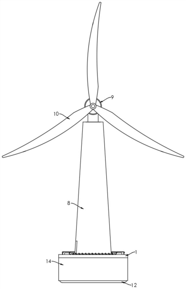
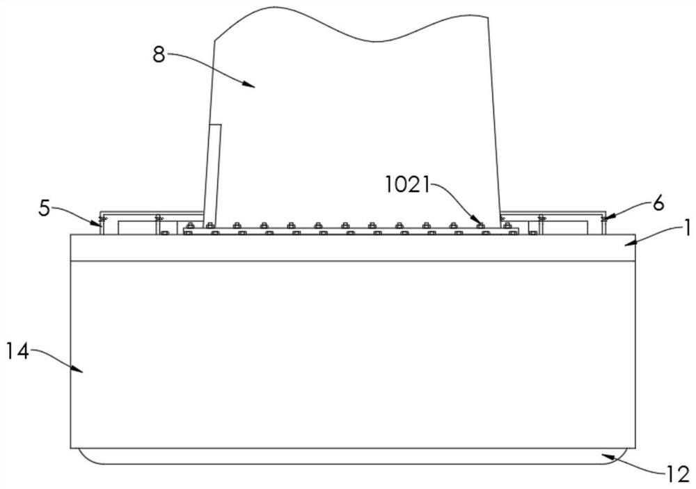
[0032] refer to Figure 1-4 , a floating wind power device with a plastic floating body, comprising

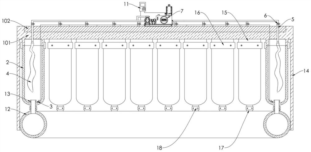
[0033] The floating platform includes a base 1, and a plurality of corresponding plastic floating bodies 2 are evenly sealed and connected downwards on the periphery of the base 1, and the bottoms of the plastic floating bodies 2 are respectively provided with corresponding water immersion sensors 3;

[0034] Protective plate 14, the base 1 includes a sheet-shaped plastic plate 101, the protective plate 14 is integrally formed and connected to the lower side of the sheet-shaped plastic plate 101, and the protective plate 14 is surrounded by the plastic floating body 2 outside of

[0035] A plurality of supporting airbags 4 are respectively arranged in the p...


PUM


Abstract

The invention relates to a floating type wind power device with plastic floating bodies. The floating type wind power device comprises a floating platform, a protective plate, a plurality of matched air bags, a wind power tower drum and a control system; the floating platform comprises a base, the periphery of the base is uniformly, downwards and hermetically connected with the plurality of corresponding plastic floating bodies, and the bottoms of the plastic floating bodies are respectively provided with corresponding water sensors; the base comprises a sheet-shaped plastic plate, and the protective plate is integrally formed and connected to the lower side of the sheet-shaped plastic plate and arranged on the outer sides of the plastic floating bodies in a surrounding mode; the plurality of matched air bags are respectively arranged in the plastic floating bodies, the air inlet ends of the matched air bags are respectively connected with corresponding air inlet pipes, and the air inlet pipes are connected to the air outlet ends of inflation pumps in parallel through corresponding electromagnetic valves; the wind power tower drum is fixedly connected to the base; and the water sensors, the electromagnetic valves and the inflation pumps are all connected to the control system. According to the floating type wind power device with the plastic floating bodies, the workload of preservative treatment can be effectively and greatly reduced, and the use safety and practicability can be effectively ensured.

Description

technical field [0001] The invention relates to a wind power device, in particular to a floating wind power device with a plastic floating body. Background technique [0002] Wind power generation refers to the conversion of wind kinetic energy into electrical energy. Wind energy is a clean and pollution-free renewable energy source. Among them, land wind power is affected by terrain, land resources and other issues, and the wind electrodes produced are limited. The construction of offshore wind power requires a huge seabed fixed platform, which requires huge construction investment and difficulty, and affects the operation of ships; while the deep sea is the most favorable area for the development of wind power resources, it is basically impossible to use the existing submarine fixed platform construction in the deep sea area. Therefore, floating wind power technology came into being. At present, the vast majority of deep-sea floating wind power basically use metal-welded ...

Claims


Application Information

Patent Timeline
Patent Type & Authority Applications(China)
IPC IPC(8): F03D9/25F03D13/25F03D1/06F03D7/02F03D17/00F03D80/00B63B35/44B29C65/02
CPCF03D9/25F03D13/25F03D1/065F03D7/02F03D17/00F03D80/00B63B35/44B29C65/02B29C66/52B63B2035/446Y02E10/72Y02E10/727
Inventor 陈建福
Owner 福建纳川管业科技有限责任公司
Why Eureka
Try Eureka