
The design method of aircraft model and its structure layout parameters in single-slider rolling spray mode with variable center of mass

A technology of aircraft and changing the center of mass, which is applied in the directions of instruments, calculations, electrical and digital data processing, etc., can solve the problems of aerodynamic rudder ablation, complex slider layout, etc., and achieve the effect of simple structure

Active Publication Date: 2017-11-17
HARBIN INST OF TECH +1
View PDF3 Cites 0 Cited by
  • Summary
  • Abstract
  • Description
  • Claims
  • Application Information

AI Technical Summary

Problems solved by technology

[0011] The purpose of the present invention is to solve the aerodynamic rudder ablation problem of traditional hypersonic aircraft, and the complex problem of internal slider layout of traditional variable center of mass aircraft

Method used


Image

  • The design method of aircraft model and its structure layout parameters in single-slider rolling spray mode with variable center of mass
  • The design method of aircraft model and its structure layout parameters in single-slider rolling spray mode with variable center of mass
  • The design method of aircraft model and its structure layout parameters in single-slider rolling spray mode with variable center of mass

Examples


specific Embodiment approach 1

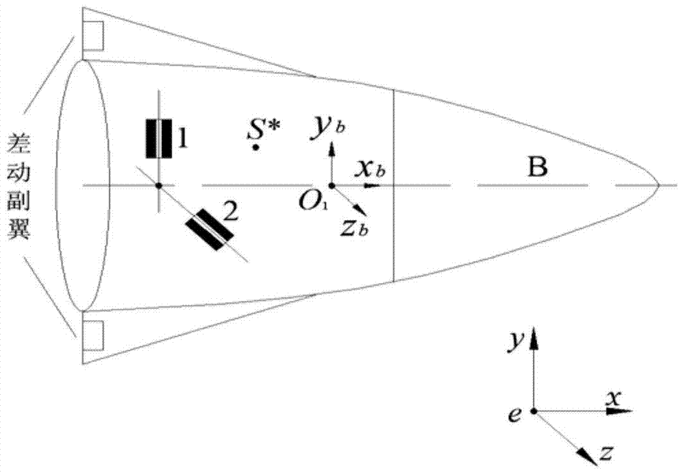
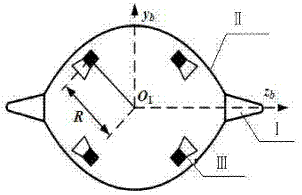
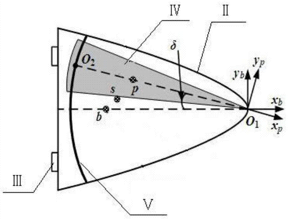
[0037] Specific embodiment one, in conjunction with Fig. 2 (a), Fig. 2 (b) and image 3 Description of this embodiment, the aircraft model with variable center of mass in the single-slider roll jet mode includes two fixed wings I, missile body II and roll jet engine III, and the two fixed wings I are symmetrically arranged on both sides of the missile body II; the aircraft The model also includes the movable body IV inside the missile body II; the movable body IV is a cone, and the tip of the cone of the movable body IV and the head of the missile body II pass through the movable connection point O 1Connection; the tail of the missile body II is provided with a guide rail V, and the root of the cone of the movable body IV is connected to the O of the guide rail V at the tail of the missile body II. 2 point sliding connection; where O on rail Ⅴ 2 Under the action of the servo force, the point circles O along the guide rail V fixedly connected with the missile body 1 Do relati...

specific Embodiment approach 2

[0038] Specific embodiment two, a kind of design method of the structural layout parameter of the single-slider rolling jet mode variable center of mass aircraft model for the single slider rolling jet mode variable center of mass aircraft comprises the following steps:

[0039] Step 1: Design the dynamic model of the aircraft:

[0040] Let the center of mass of the aircraft be s, the center of mass of the missile body II be b, and the center of mass of the movable body IV be p; the following systems all refer to the variable center of mass aircraft; the degrees of freedom of the system include the three-dimensional translation and three-dimensional rotation of the variable center of mass aircraft, and The two-dimensional rotation of the movable body IV; the whole system is regarded as a multi-rigid body system composed of the projectile II and the movable body IV, O 1 , O 2 is the connection point of the two components; the dynamic model is established using the momentum mom...

specific Embodiment approach 3

[0051] Specific embodiment three: the design process of the dynamic model of step one aircraft in the present embodiment is as follows:

[0052] Step 1.1, define the coordinate system and parameters

[0053] In order to describe the dynamic model of the variable center of mass aircraft, three coordinate systems are defined, namely the inertial coordinate system, the projectile coordinate system and the movable body fixed coordinate system, where the origin of the projectile coordinate system is at the warhead O 1 Office, O 1 x b The axis is along the longitudinal axis of projectile II, pointing to the head is positive, O 1 the y b axis perpendicular to O 1 x b axis and parallel to the longitudinal axis of guide rail V, O 1 z b axis and the other two axes form a right-handed coordinate system; the origin of the fixed coordinate system of the movable body is also at the warhead O 1 , O 1 x p The axis is along the longitudinal axis of the movable body IV, O 1 the y p ...


PUM


Abstract

A single sliding block rolling spray mode variable centroid aircraft model and a designing method for structural layout parameters thereof relate to the field of flight vehicle design, and aim to solve the problems of ablation to an aerodynamic rudder in a conventional hypersonic aircraft and complexity in sliding block layout inside a conventional variable centroid aircraft. The aircraft model provided by the invention comprises two fixed wings, a projectile body, a rolling spray engine and a movable body, wherein the two fixed wings are symmetrically arranged on the two sides of the projectile body; the tip of the cone-shaped body of the movable body is connected with the head of the projectile body through a movably connecting point O1; a guide rail is arranged at the tail end of the projectile body, the root part of the cone-shaped body of the movable body is connected with the O2 point of the guide rail at the tail part of the projectile body in a sliding manner; since the movable body is further expanded to serve as a main body, the mass of the movable body accounts for most part of the mass of the entire system, the projectile body is taken as a driven body, the purpose of maneuvering control can also achieved, the motion of the projectile body can be controlled through an actuator on the movable body; the integral aerodynamic configuration of the projectile body is ensured. The aircraft model provided by the invention is applicable to the field of flight vehicle design.

Description

technical field [0001] The invention relates to an aircraft with variable center of mass and a method for designing parameters of the aircraft. Background technique [0002] Variable center of mass control technology is to achieve the desired control performance by actively moving the movable mass body inside the aircraft, changing the position of the center of mass of the system, and causing the external torque acting on the aircraft to change, so as to achieve the purpose of maneuvering the aircraft. [0003] According to different implementation methods, they can be divided into two categories: (1) Moving-mass trim control (MMTC); (2) Moving-mass roll control (MMRC). Variable center of mass trim control (MMTC) is mainly applied to aircraft with axisymmetric structure. It generates trim angle of attack through the movement of internal movable mass body, so as to make the aircraft maneuver. Variable center of mass rolling control (MMRC) is mainly applied to aircraft with s...

Claims


Application Information

Patent Timeline
Patent Type & Authority Patents(China)
IPC IPC(8): G06F17/50
Inventor 高长生李涧青魏鹏鑫荆武兴
Owner HARBIN INST OF TECH
Learn More