Multi-cell automobile energy-absorbing buffer device

A buffer device, automobile technology, applied in vehicle parts, transportation and packaging, vehicle safety arrangement, etc., to achieve the effect of improving energy absorption efficiency, increasing flexibility, and simple structure

Inactive Publication Date: 2015-09-09
HUNAN UNIV
View PDF5 Cites 21 Cited by
  • Summary
  • Abstract
  • Description
  • Claims
  • Application Information

AI Technical Summary

Problems solved by technology

[0004] Aiming at the problems existing in the existing automobile energy-absorbing buffer devices, the present invention provide...

Method used


Image

  • Multi-cell automobile energy-absorbing buffer device
  • Multi-cell automobile energy-absorbing buffer device
  • Multi-cell automobile energy-absorbing buffer device

Examples


Embodiment 1

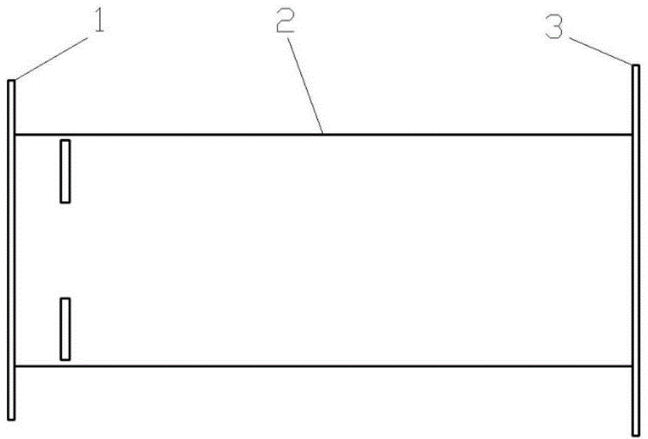
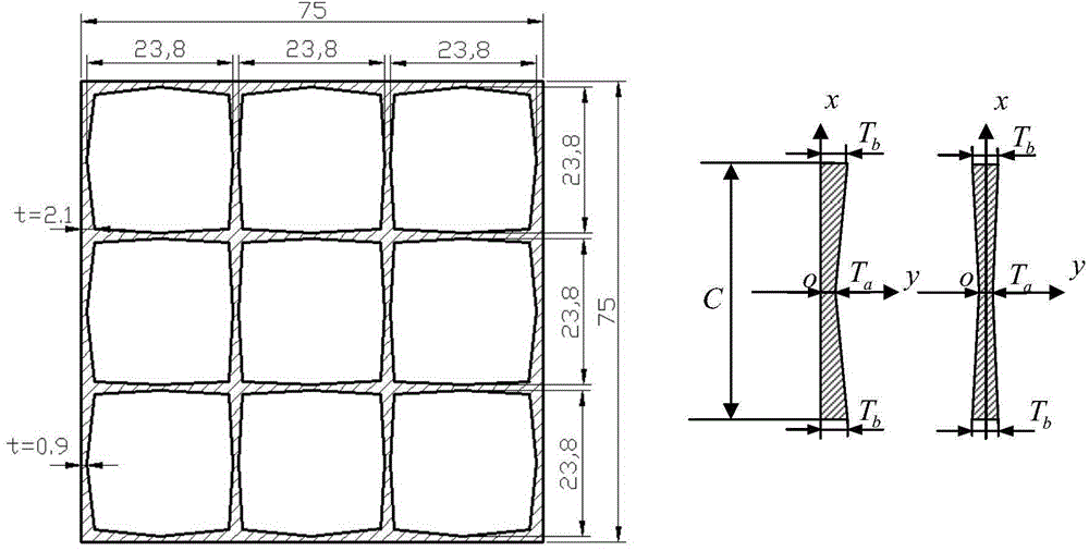
[0034] like Figure 1-3 As shown, in this embodiment, the buffer energy-absorbing device is composed of a nine-cell gradient square thin-walled tube (2), a front-end mounting plate (1) and a rear-end mounting plate (3). The main structure of the buffer energy-absorbing device in this embodiment—the multi-cell energy-absorbing tube 2 adopts a nine-cell gradient square thin-walled energy-absorbing buffer structure. Metal preparation. The dimensions of the cross-section of the gradient square thin-walled tube are as figure 2 as shown, figure 2 The unit of each dimension is mm. The nine-cell gradient square thin-walled tube is connected to the bumper through the front-end mounting plate 1, and connected to the front longitudinal beam through the rear-end mounting plate 2.

[0035] In this embodiment, the nine-cell gradient square thin-walled tube has an axial length of 200 mm, an external dimension of the cross section of 75 mm×75 mm, and an equivalent thickness of the tube ...

Embodiment 2

[0048] Image 6 A schematic diagram of the three-dimensional structure of another buffer energy-absorbing device of the present invention is shown. The corner cell structures are connected by 4 thin-walled connecting plates, thus forming 4 corner cell structures and the central cavity cell structure, that is, the five-cell structure, such as Image 6 shown. The corner cells and the central cavity cell structure are extruded from light alloy materials at one time, and are connected to the bumper through the front mounting plate, and the rear mounting plate is connected to the front longitudinal beam. A series of induction grooves are set 15mm away from the collision end. The specific size is as Image 6 , 7 shown. The setting of induction tanks is different from that of traditional induction tanks in that they are arranged at intervals rather than continuously. The main purpose lies in two aspects: first, to reduce the peak force of the initial collision; second, to guide ...


PUM

PropertyMeasurementUnit
Axial lengthaaaaaaaaaa
Thicknessaaaaaaaaaa

Abstract

The invention discloses a gradient multi-cell automobile energy-absorbing buffer device which comprises a gradient multi-cell energy-absorbing pipe (2). The gradient multi-cell energy-absorbing pipe (2) comprises a plurality of cells, a plurality of side walls are enclosed to form each cell, and the thickness of each side wall is changed in a gradient manner, namely, the thickness of each side wall is gradually decreased by a preset gradient from the edge of the side wall to the middle of the side wall. Light metal materials can be extruded to form an energy-absorbing buffer structure. A multi-cell structure is arranged on the cross section of the gradient multi-cell automobile energy-absorbing buffer device, the deformation mode of the structure is more stable as compared with a traditional single pipe energy-absorbing structure, and energy-absorbing efficiency is higher. Compared with an equal-thickness multi-cell structure, a portion making a great contribution to structural plastic deformation performance is effectively enhanced by gradient thickness change, and a portion making a small contribution to deformation performance is weakened. The gradient multi-cell automobile energy-absorbing buffer device serves as a direct impact energy-absorbing structure for an automobile, direct impact safety of the automobile can be greatly enhanced, and automobile passenger casualties are reduced.

Description

technical field [0001] The invention mainly relates to the field of automobile collision safety structure design, in particular to a gradient multicellular automobile buffer energy-absorbing device. Background technique [0002] With the increase of automobile ownership, automobile collision safety is paid more and more attention by people. In order to protect the safety of the occupants in the event of a car collision, car developers have designed a buffer energy-absorbing device at the front of the car to absorb the energy of the collision, including car bumpers, car buffer and energy-absorbing boxes, etc. Metal thin-walled beam structural parts are widely used in collision kinetic energy dissipation systems of almost all vehicles such as automobiles, ships and aircrafts because of their simple structure and ease of manufacture. When subjected to the impact load, the metal thin-walled beam member mainly relies on its own plastic deformation to absorb the impact kinetic en...

Claims


Application Information

Patent Timeline
IPC IPC(8): B60R19/34
CPCB60R19/34B60R2019/264
Inventor 郑刚孙光永李光耀庞通
Owner HUNAN UNIV
Why Eureka
Try Eureka