Multi-rotor-wing unmanned aerial vehicle for panoramic shooting

A multi-rotor UAV and panoramic shooting technology, which is applied in the field of UAV design for panoramic photography, can solve the problems of complex structure, large difference, and unusability, etc., and achieve extremely light weight and simple structure. Effect

Inactive Publication Date: 2015-09-09
TIANJIN UNIV
View PDF10 Cites 27 Cited by
  • Summary
  • Abstract
  • Description
  • Claims
  • Application Information

AI Technical Summary

Problems solved by technology

[0013] (a) The structure is complex and can only be applied to multi-rotor aircraft with "I"-shaped planes
Most current multicopters cannot take advantage of this design
[0014] (b) The position difference between the upper and lower cameras is still too large, which does not solve the problem that the absolute height of the upper and lower cameras needs to be consistent when shooting

Method used


Image

  • Multi-rotor-wing unmanned aerial vehicle for panoramic shooting
  • Multi-rotor-wing unmanned aerial vehicle for panoramic shooting
  • Multi-rotor-wing unmanned aerial vehicle for panoramic shooting

Examples


Embodiment 1

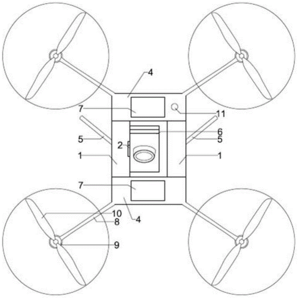
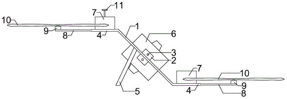
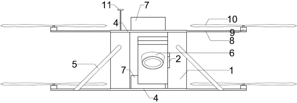
[0033] Such as Figure 1 to Figure 3 As shown, the multi-rotor UAV for panoramic shooting provided by the present invention includes a fuselage plate, and the fuselage plate is composed of two horizontal fuselage plates 4 and a tilting machine for connecting the two horizontal fuselage plates in the middle. Body plate 1 constitutes, and the inclination angle of inclined body plate is preferably 45 degrees. Each of the two horizontal fuselage plates is equipped with an equipment compartment 7 for installing electronic components such as batteries, autopilots, and motor governors. At the same time, four motor cantilevers 8 are evenly distributed on the two horizontal fuselage plates. Each motor cantilever is respectively equipped with a motor 9 and a rotor 10, and the inclined fuselage plate is equipped with two landing gears 5 that are inclined outwards (together to form a figure-eight) on one side of the ground, so as to prevent the multi-rotor from landing on the ground. Til...


PUM


Abstract

The invention relates to a multi-rotor-wing unmanned aerial vehicle for panoramic shooting. The multi-rotor unmanned aerial vehicle comprises unmanned aerial vehicle body plates, wherein equipment compartments and four motor cantilevers are arranged on the unmanned aerial vehicle body plates, a motor and a rotor wing are arranged on each motor cantilever, the unmanned aerial vehicle body plates comprise two horizontal unmanned aerial vehicle body plates and a middle inclined unmanned aerial vehicle body plate for connecting the two horizontal unmanned aerial vehicle body plates, cameras are arranged on the upper side surface and the lower side surface of the inclined unmanned aerial vehicle body plate, and an undercarriage is arranged at one side, facing the ground, of the inclined unmanned aerial vehicle body plate. The multi-rotor unmanned aerial vehicle for panoramic shooting can realize shooting without blind area, and can meet the requirement on panoramic shooting in short distance and confined space of heritage, the location difference of the cameras is minimized, the image splicing accuracy is high, the shooting speed is high, the drifting interference is low, and an unmanned aerial vehicle body is light and small, and can realize flight in confined space easily.

Description

technical field [0001] The invention belongs to the technical field of drone design for panoramic photography. Background technique [0002] 360-degree panoramic photography refers to the camera rotating at a fixed point to take panoramic photos of surrounding 360*180-degree (horizontal 360-degree, vertical 180-degree) scenery. Change the viewing angle (direction) to create the feeling of being able to look around and being in the scene. [0003] Panoramic photography has developed rapidly and has gradually become a type of virtual reality technology. Compared with horizontal movement, shooting at a high place has a wider field of vision and can see more scenery. Unmanned helicopters and unmanned multi-rotor aircraft have been used to capture aerial panoramic images. [0004] The most common shooting method of unmanned helicopters is mainly to install a single camera under the gimbal, and rely on the ability of the helicopter to rotate around its own hovering center to co...

Claims


Application Information

Patent Timeline
Patent Type & Authority Applications(China)
IPC IPC(8): B64C39/08B64C27/08B64D47/08
Inventor 李哲周成传奇柴亚隆邵浩然闫宇
Owner TIANJIN UNIV
Why Eureka
Try Eureka