
UAV panorama shooting platform in limited space

A technology of limited space and PTZ, applied in the direction of using feedback control, etc., can solve the problems of unavailability, too large difference, complicated structure, etc., and achieve the effect of simple installation, small quantity and light weight.

Inactive Publication Date: 2017-07-11
TIANJIN UNIV
View PDF4 Cites 0 Cited by
  • Summary
  • Abstract
  • Description
  • Claims
  • Application Information

AI Technical Summary

Problems solved by technology

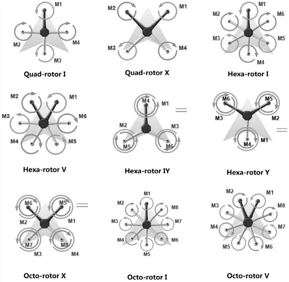
[0013] (a) The structure is complex and can only be applied to multi-rotor aircraft with "I"-shaped planes
Most current multicopters cannot take advantage of this design
[0014] (b) The position difference between the upper and lower cameras is still too large, which does not solve the problem that the absolute height of the upper and lower cameras needs to be consistent when shooting

Method used


Image

  • UAV panorama shooting platform in limited space
  • UAV panorama shooting platform in limited space
  • UAV panorama shooting platform in limited space

Examples


Embodiment

[0041] 1. UAV panorama shooting platform in limited space

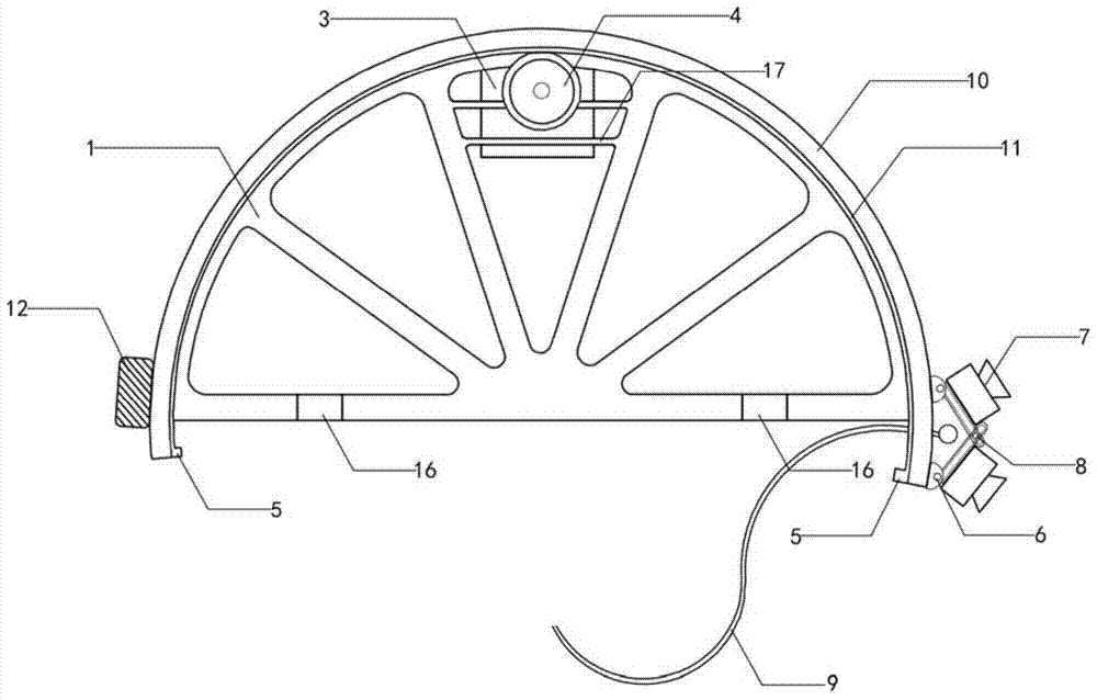
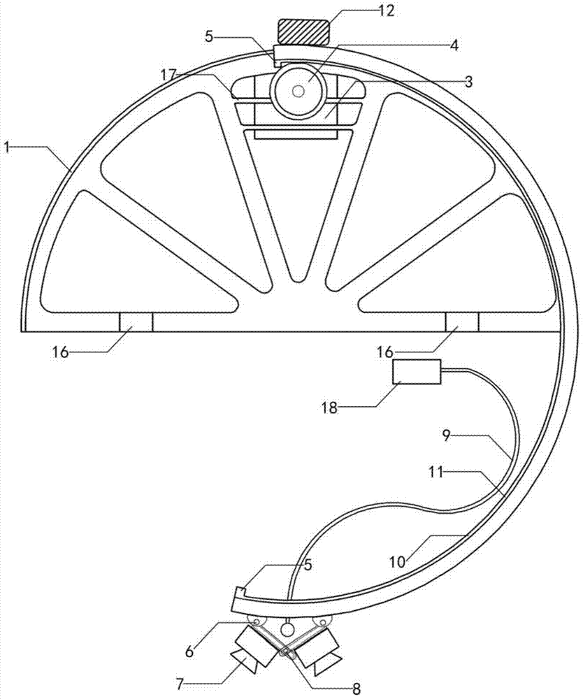
[0042] Such as Figure 2 to Figure 7 As shown, the UAV panoramic shooting platform in the limited space provided by the present invention includes a fan-shaped fixing bracket 1 for fixing on the UAV fuselage, and the fan-shaped central angle of the fan-shaped fixing bracket is 180 degrees. A rotating arm 10 is installed on the outer edge circumference of the fan-shaped fixed support, and a rotating arm plug 5 is respectively provided at the two ends of the rotating arm, and an orbital movement pair is formed between the rotating arm and the outer edge circumference of the fan-shaped fixed support, and the fan-shaped fixed support A steering gear 3 is installed on the steering gear mounting bracket 17, and a rotating arm driving wheel 4 is coaxially installed on the steering gear rotating shaft. A rotating driving pair is formed between the driving wheel and the rotating arm, and the rotating driving pair can be Be th...


PUM


Abstract

A panoramic shooting gimbal in a limited space, including fan -shaped fixed brackets for fixing on the body of unmanned multi -rotor aircraft. A rotating arm is installed on the outer edge of the fan -shaped fixed bracket.The rail movement is formed between the outer edge of the bracket, and a steering gear is installed on the fan -shaped fixed bracket. A rotary arm drive wheel is installed on the coaxial shaft on the rotating shaft.The rotating driver, the rotating arm is installed with a camera through the camera seat.The present invention can meet at the same time: completely non -blind shots, meet the requirements of close range of the inheritance and panoramic shooting requirements in the limited space; the space between the spaces between each camera is good, and the accuracy of the image stitching is high; there is no particular restriction on the number of cameras or lenses;Light weight, small volume, and easy to achieve limited space flight; suitable for most of the existing multi -rotor machines, obtaining the same shooting effect (strong generality on multi -rotor machines is the characteristics of this solution).

Description

technical field [0001] The invention belongs to the technical fields of digitization of architectural heritage, unmanned aerial vehicle platform design and panoramic photography. Background technique [0002] 360-degree panoramic photography refers to the camera rotating at a fixed point to take panoramic photos of surrounding 360*180-degree (horizontal 360-degree, vertical 180-degree) scenery. Change the viewing angle (direction) to create the feeling of being able to look around and being in the scene. [0003] Panoramic photography has developed rapidly and has gradually become a type of virtual reality technology. Compared with horizontal movement, shooting at a high place has a wider field of vision and can see more scenery. Unmanned helicopters and unmanned multi-rotor aircraft have been used to capture aerial panoramic images. [0004] The most common shooting method of unmanned helicopters is mainly to install a single camera under the gimbal, and rely on the abil...

Claims


Application Information

Patent Timeline
Patent Type & Authority Patents(China)
IPC IPC(8): G05D3/12
Inventor 李哲闫宇邵浩然柴亚隆周成传奇
Owner TIANJIN UNIV
Learn More