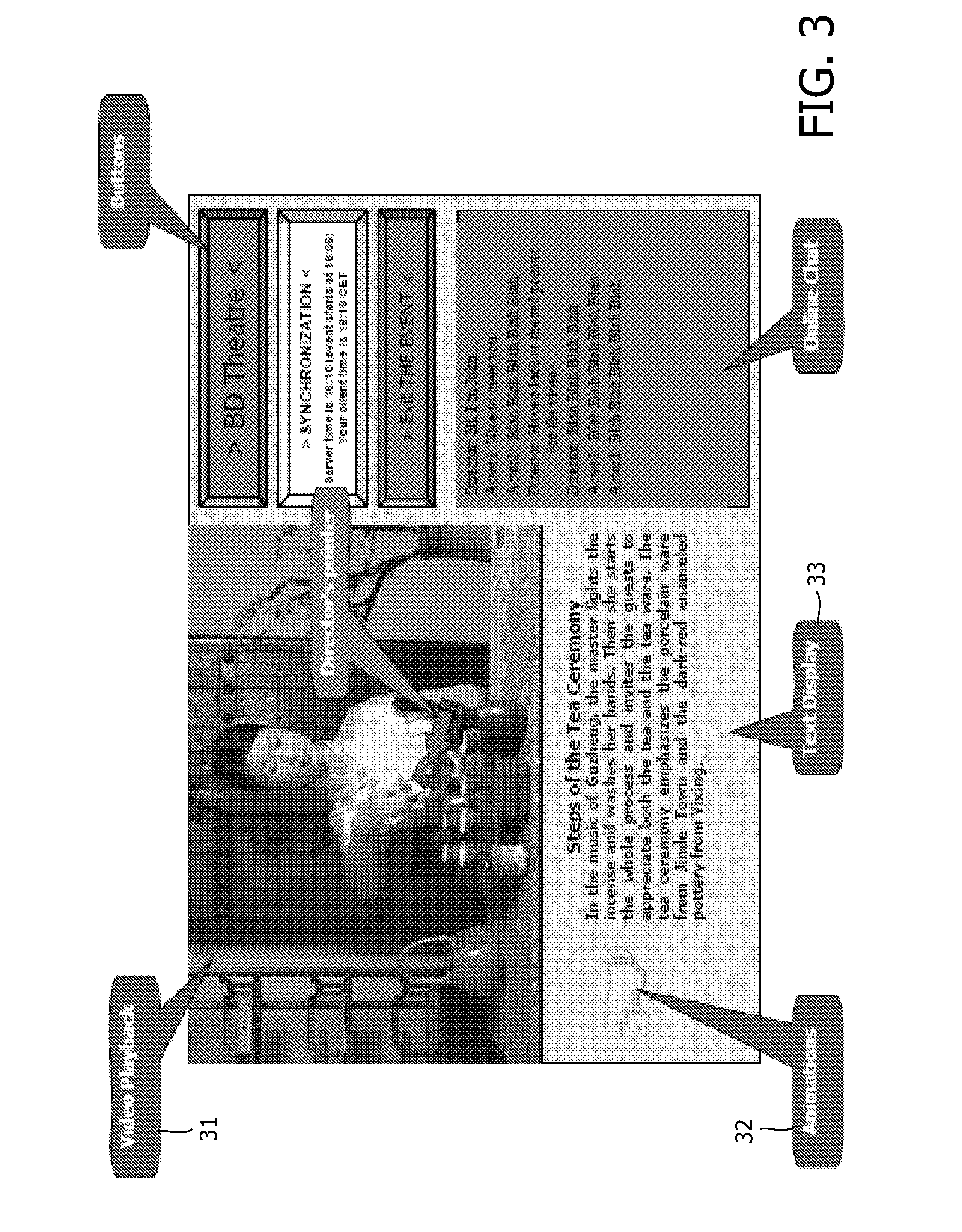
3 menu display

a 3d-image and menu technology, applied in the field of rendering visual information, to achieve the effect of reducing range, avoiding confusing mix-up of elements, and facilitating mapping

Inactive Publication Date: 2010-04-15
KONINKLIJKE PHILIPS ELECTRONICS NV
View PDF11 Cites 57 Cited by
  • Summary
  • Abstract
  • Description
  • Claims
  • Application Information

AI Technical Summary

Benefits of technology

[0011]The measures have the effect that each set of image information is assigned it's own, separate depth range. Because the first and second depth ranges do not overlap, occlusion of elements in the image data located in a front (second) depth range by protruding elements of a more backward (first) depth sub-range is prevented. Advantageously the user is not confused by intermingling of 3D objects of various image sources.
[0012]The invention is also based on the following recognition. Displaying 3D image information of various sources may be required on a single 3D display system. The inventors have seen that, as various elements have different depths, a combined image on a display might be confusing to a user. For example, some elements of a video application in the background may move forward and unexpectedly (partly) occlude graphical elements located on a more forward position. For some applications such overlap may be predictable, and a suitable depth position for various elements may be adjusted while authoring such content. However, the inventors have seen that in many situations a combination is to be displayed that is unpredictable. Determining the sub-ranges for combined display, and assigning a non-overlapping sub-range to each source, avoids confusing mix-up of elements of different sources at different depths.
[0013]In an embodiment of the method said accommodating comprises compressing the image depth range to fit in the first sub-range, and / or compressing the secondary depth range to fit in the second sub-range. This has the advantage that the original image information depth information is converted into the available sub-range, while maintaining the original depth structure for each set of image information in a reduced range.
[0014]In an embodiment of the method the output information includes image data and a depth map for positioning the image data along the depth dimension of the 3D display according to depth values, and the method comprises determining, in the depth map, a first sub-range of depth values and second sub-range of depth values as the first sub-range and the second sub-range. This has the advantage that the sub-ranges can be easily mapped onto respective value ranges in the depth map.

Problems solved by technology

However, the document does not discuss the options of real depth 3D display systems, and displaying various image information elements on such display systems.

Method used


Image

  • 3 menu display
  • 3 menu display
  • 3 menu display

Examples


Embodiment Construction

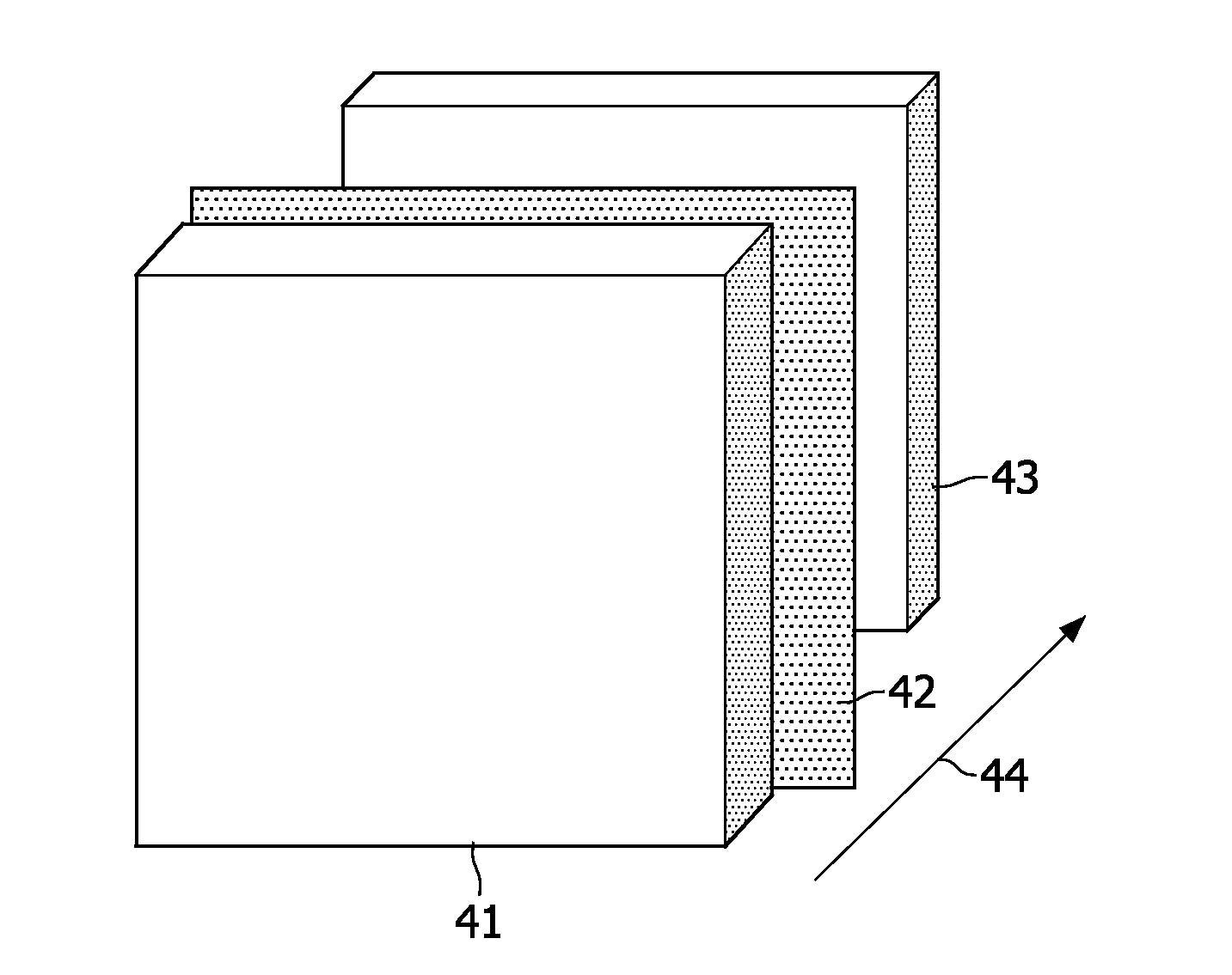
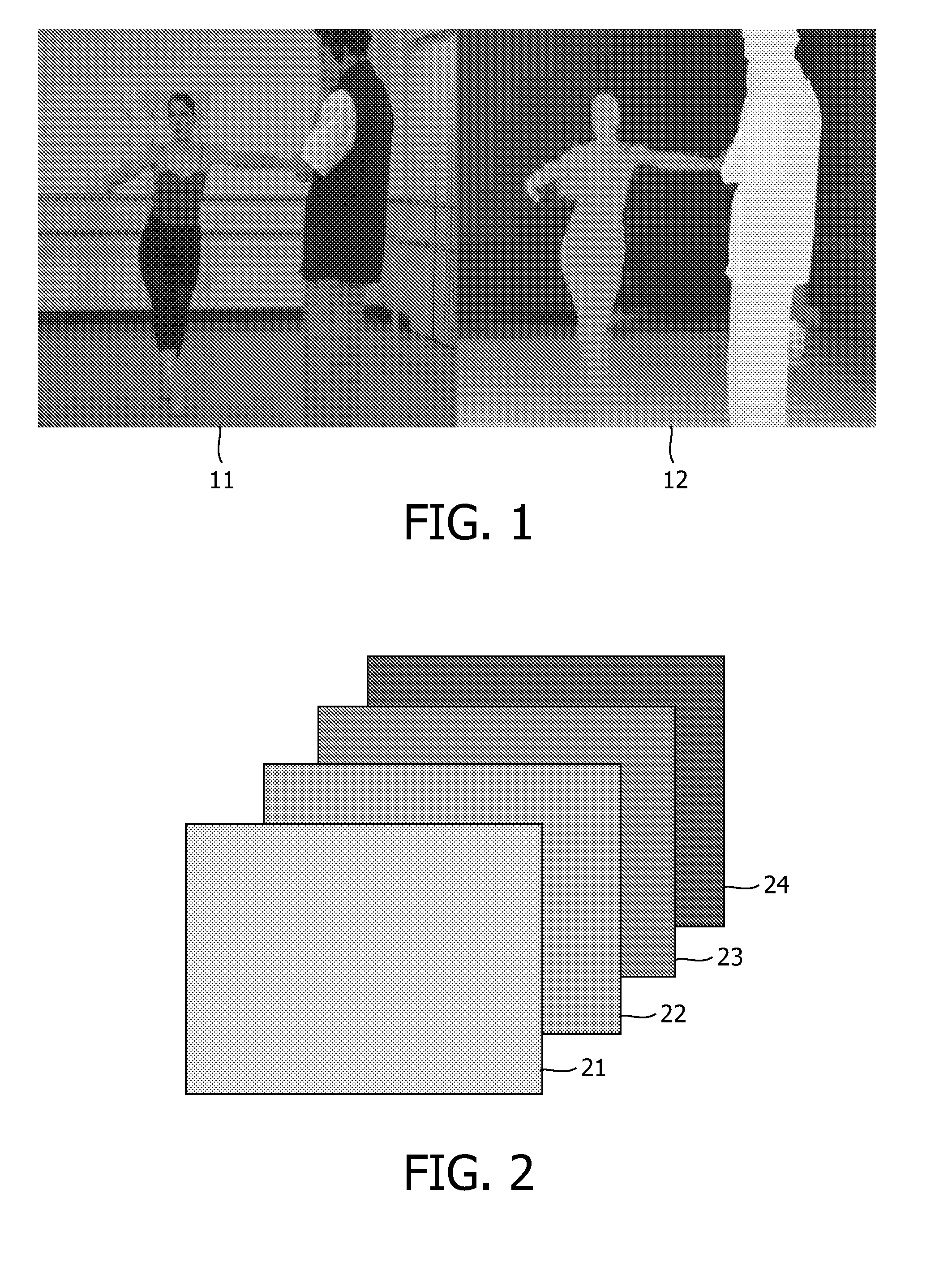
[0023]The following section provides an overview of three-dimensional [3D] displays and perception of depth by humans. 3D displays differ from 2D displays in the sense that they can provide a more vivid perception of depth. This is achieved because they provide more depth cues then 2D displays which can only show monocular depth cues and cues based on motion.

[0024]Monocular (or static) depth cues can be obtained from a static image using a single eye. Painters often use monocular cues to create a sense of depth in their paintings. These cues include relative size, height relative to the horizon, occlusion, perspective, texture gradients, and lighting / shadows. Oculomotor cues are depth cues derived from tension in the muscles of a viewers eyes. The eyes have muscles for rotating the eyes as well as for stretching the eye lens. The stretching and relaxing of the eye lens is called accommodation and is done when focusing on a image. The amount of stretching or relaxing of the lens musc...


PUM


Abstract

A device and method of rendering visual information combine image information like video and secondary image information, like graphics. The image information and the secondary image information are processed for generating output information to be rendered in a three-dimensional space. The output information is arranged for display on a 3D stereoscopic display having a true display depth range (44). The processing includes detecting an image depth range of the image information, and detecting a secondary depth range of the secondary visual information. In the display depth range (44), a first sub-range (41) and second sub-range (43) are determined, which first sub-range and second sub-range are non-overlapping. The image depth range is accommodated in the first sub-range and the secondary depth range is accommodated in the second sub-range. Advantageously graphics and video are displayed in true 3D without video objects occluding graphical objects.

Description

FIELD OF THE INVENTION[0001]The invention relates to a method of rendering visual information, which method comprises receiving image information, receiving secondary image information to be rendered in combination with the image information, processing the image information and the secondary image information for generating output information to be rendered in a three-dimensional space.[0002]The invention further relates to a device for rendering visual information, the device comprising input means for receiving image information, and receiving secondary image information to be rendered in combination with the image information, and processing means for processing the image information and the secondary image information for generating output information to be rendered in a three-dimensional space.[0003]The invention further relates to a computer program product for rendering visual information.[0004]The invention relates to the field of rendering image information on three-dimens...

Claims


Application Information

Patent Timeline
Patent Type & Authority Applications(United States)
IPC IPC(8): G06T15/00G06T19/00
CPCH04N13/0011H04N2213/003H04N13/0497H04N13/007H04N13/111H04N13/183H04N13/398
Inventor NEWTON, PHILIP S.LI, HONGHE, DARWIN
Owner KONINKLIJKE PHILIPS ELECTRONICS NV
Why Eureka
Try Eureka