Antihelix-conforming ear-mount for personal audio-set

a technology for personal audio-sets and ear-mounts, which is applied in the direction of intra-aural earpieces, mouthpiece/microphone attachments, diagnostics, etc., can solve the problems of large volume of mounts, wearers feel discomfort supporting personal audio-sets, and most ear-clip designs do not easily lend themselves to being worn over either the left or right ear of wearers, so as to increase the passive attenuation of the system and minimize the effect of pneumatic leak

a technology for personal audio-sets and ear-mounts, which is applied in the direction of intra-aural earpieces, mouthpiece/microphone attachments, diagnostics, etc., can solve the problems of large volume of mounts, wearers feel discomfort supporting personal audio-sets, and most ear-clip designs do not easily lend themselves to being worn over either the left or right ear of wearers, so as to increase the passive attenuation of the system and minimize the effect of pneumatic leak

US20090226025A1Inactive Publication Date: 2009-09-10LOGITECH EURO SA

Image

  • Antihelix-conforming ear-mount for personal audio-set
  • Antihelix-conforming ear-mount for personal audio-set
  • Antihelix-conforming ear-mount for personal audio-set

Examples


Embodiment Construction

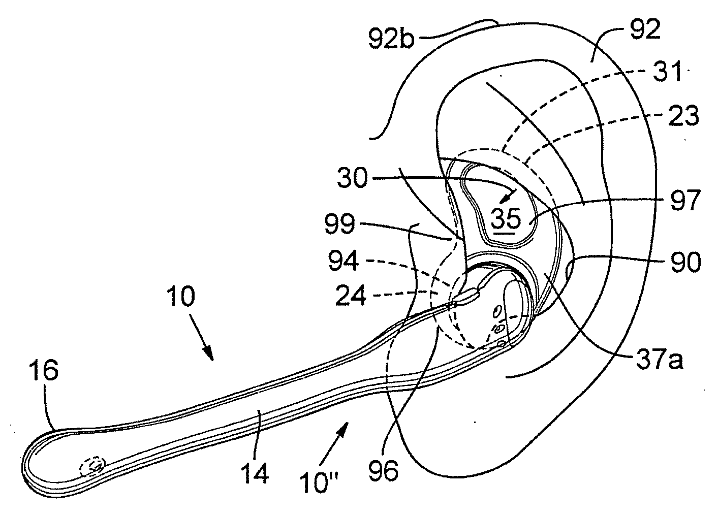
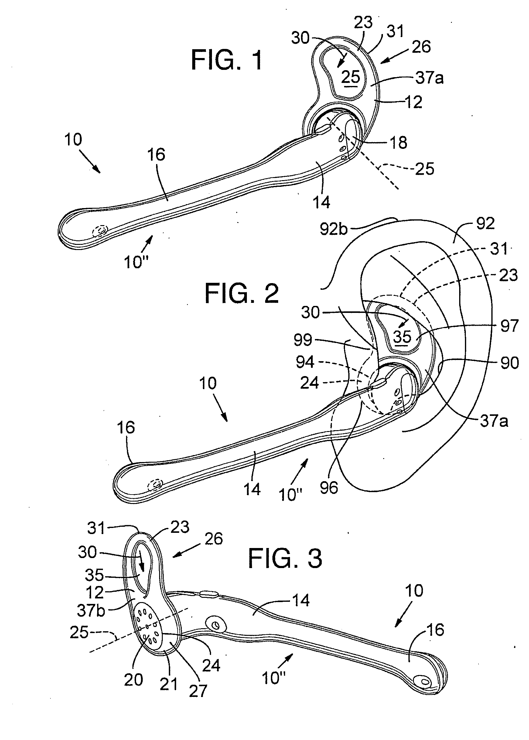
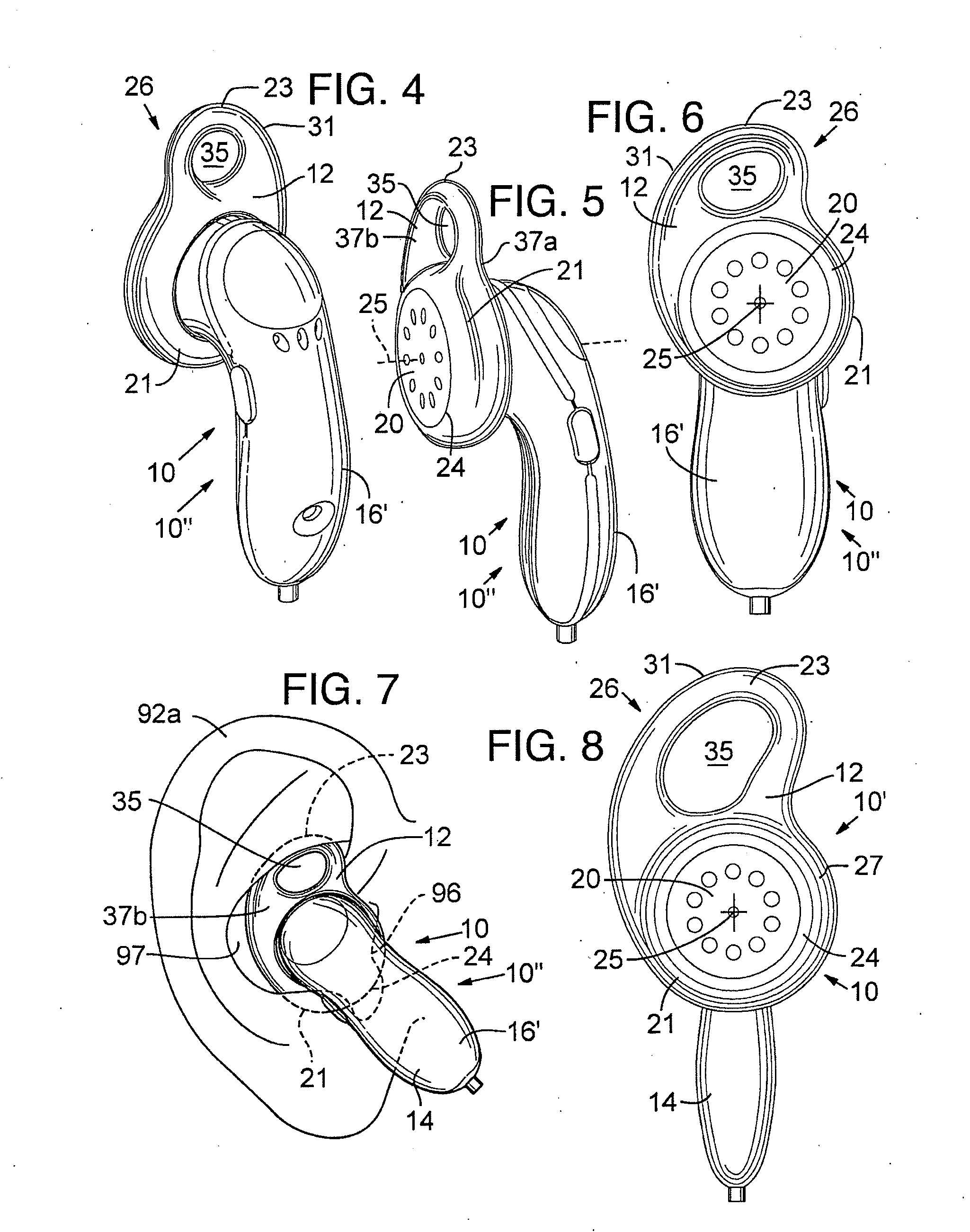
[0029]A personal audio-set 10, such as a head phone, earphone 10′ (FIGS. 8 and 13-15), or headset 10″ (FIGS. 1-7, and 9-12), that includes a compressible mounting portion 12 that compresses to conform with the antihelix 90 of the wearer's ear 92 thereby detachably securing the personal audio-set 10 within the wearer's ear 92 is disclosed in FIGS. 1-15.

Kidney-Shaped Ear Loop

[0030]In a first preferred embodiment, shown in FIGS. 1-3, the personal audio-set 10 is a headset 10″ having a frame 14 with a boom microphone 16 extending longitudinally from an ear bud 18. The ear bud 18 preferably contains driver or other audio transducer (collectively referred to herein as a “speaker 20” or earphone), and wiring (not shown) usually extends from the headset 10″ to operably connect the headset 10″ to an appropriate audio device (not shown).

[0031]As best shown in FIG. 2, the ear bud 18 is sized to be received within a wearer's ear 92 such that the speaker 20 is positioned over the ear canal 94 of...


PUM


Abstract

A light weight and comfortable ear mount for a personal audio-set is disclosed. The ear mount conforms with the antihelix of a wearer's ear, thereby operating substantially as a compression spring between the wearer's antihelix and tragus, to operably secure the personal audio-set in place. In a preferred embodiment, the ear-mount is substantially kidney-shaped and includes an opening to prevent the total occlusion of the ear canal by the personal audio-set. Alternatively, the ear-mount includes a loop of material sized to operably engage the antihelix of the wearer's ear. The ear-mount is preferably reversible to allow it to be placed in either the wearer's left or right ear.

Description

CROSS-REFERENCES TO RELATED APPLICATIONS[0001]This application is a continuation of, and claims priority to, U.S. application Ser. No. 10 / 358,120 entitled “Antihelix-Conforming Ear-Mount For Personal Audio-Set”, filed on Feb. 3, 2003, which claims priority to U.S. Provisional Application No. 60 / 361,490 entitled “Antihelix-Conforming Ear-Mount For Personal Audio-Set”, filed on Mar. 2, 2002, and which is a continuation-in-part of, and claims priority to, the following U.S. Design Applications: U.S. Design Application No. 29 / 161,922, filed on Jun. 5, 2002, which issued as U.S. Design Patent No. D469,755 on Feb. 4, 2003; U.S. Design Application No. 29 / 161,923, filed on Jun. 5, 2002, which issued as U.S. Design Patent No. D470,128 on Feb. 11, 2003; U.S. Design Application No. 29 / 161,924, filed on Jun. 5, 2002, which issued as U.S. Design Patent No. D470,122 on Feb. 11, 2003; and U.S. Design Application No. 29 / 161,926, filed on Jun. 5, 2002, which issued as U.S. Design Patent No. D470,123...

Claims


Application Information

Patent Timeline
10 Sep 2009
Publication
US20090226025A1
IPC
H04R25/00; H04R1/08; H04R1/10
CPC
H04R1/083; H04R2201/107; H04R1/105; H04R1/1016
Inventors
HOWES, MICHAEL; AMAE, DOMINIC