A conveying device used in an automated production line

A technology of automatic production line and conveying device, applied in the direction of conveyor, transportation and packaging, can solve the problems of reduced production efficiency, continuous work, long welding time of the frame, etc., to achieve convenient operation, economical and practical, simple structure. Effect

Active Publication Date: 2017-06-16
广东德信模钢实业有限公司
View PDF9 Cites 0 Cited by
  • Summary
  • Abstract
  • Description
  • Claims
  • Application Information

AI Technical Summary

Problems solved by technology

At present, the transportation method adopted is that the workers use small carts to carry the trucks, and the stacking of the frames often occurs, which leads to the failure of continuous work at different stations and reduces the production efficiency. In addition, manual transportation is more labor-intensive, and it also increases the company's workload. Labor cost
Although there are currently continuous production lines on the market, these production lines are conveyed by belts and require a large production space. In addition, due to the long welding time of the frame, similar production lines are not suitable for frame production. Enterprises, the conveying device on some automated production lines lacks a device that helps realize the lifting function of the hook, which is not convenient for the operator to adjust the height of the hook according to needs, and the conveying device on some automated production lines lacks a spring that helps And the limit device of the positioning plate cannot meet the needs of the actual situation

Method used


Image

  • A conveying device used in an automated production line

Examples


Embodiment Construction

[0012] In order to make the object, technical solution and advantages of the present invention clearer, the present invention will be further described in detail below in conjunction with the accompanying drawings and embodiments. It should be understood that the specific embodiments described here are only used to explain the present invention, not to limit the present invention.

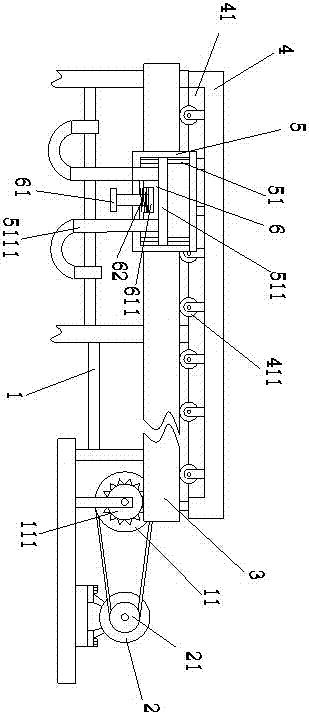
[0013] see figure 1 , figure 1 It is a structural schematic diagram of the present invention.

[0014] Described a kind of conveying device that is used on the automatic production line comprises fixed frame 1, motor 2, conveyer chain 3 and balance frame 4, and the right end of described fixed frame 1 is equipped with pulley B 11, and described motor 2 passes pulley First 21 is connected with pulley second 11, and described pulley second 11 is connected with sprocket 111 by shaft, and described sprocket 111 is also connected with conveyor chain 3, and pulley first 21 is installed on the described...


PUM


Abstract

The invention relates to a conveying device for an automatic production line. The conveying device comprises a fixed frame, a motor, a conveying chain and a balance frame, wherein a guide wheel groove is formed in the balance frame; and a guide wheel is mounted in the guide wheel groove, and is mounted on the conveying chain. The conveying device further comprises a suspension base; a guide column is arranged in the suspension base; a lifting plate is mounted on the guide column; hanging hooks are symmetrically arranged at the two sides of the lifting plate; an ejection sleeve is arranged between the hanging hooks; a screw rod is mounted at the lower end of the ejection sleeve; a positioning disc is arranged at the upper end of the screw rod; a spring is mounted on the screw rod; and the screw rod is additionally mounted on the suspension base. As the guide column having the lifting plate and the screw rod having the spring are arranged, the realization of the lifting function of the hanging hooks is facilitated, and the heights of the hanging hooks are convenient to be adjusted by operators as required; the ejection sleeve is arranged, so that the limitation of the spring and the positioning disc is facilitated; and the conveying device is simple in structure, convenient to operate, economical and practical.

Description

technical field [0001] The invention relates to the technical field of production line conveying equipment, in particular to a conveying device used in an automated production line. Background technique [0002] During the welding process of the bicycle frame, in order to improve the production efficiency, it needs to go through different processes. Due to the different processes, the frame needs to be transferred to the corresponding station. At present, the transportation method adopted is that the workers use small carts to carry the trucks, and the stacking of the frames often occurs, which leads to the failure of continuous work at different stations and reduces the production efficiency. In addition, manual transportation is more labor-intensive, and it also increases the company's workload. Labor costs. Although there are currently continuous production lines on the market, these production lines are conveyed by belts and require a large production space. In addition...

Claims


Application Information

Patent Timeline
Patent Type & Authority Patents(China)
IPC IPC(8): B65G21/12
CPCB65G21/12
Inventor 张玉雯
Owner 广东德信模钢实业有限公司
Why Eureka
Try Eureka