
Steel tube conveying device

A technology of conveying device and steel pipe, applied in the directions of transportation and packaging, conveyor objects, etc., can solve the problems of surface damage of steel pipe, severe collision and wear of steel pipe, large energy consumption, etc., and achieves the effect of simple operation, reasonable design and guarantee of integrity.

Inactive Publication Date: 2015-09-09
济宁华奇经贸有限公司
View PDF8 Cites 1 Cited by
  • Summary
  • Abstract
  • Description
  • Claims
  • Application Information

AI Technical Summary

Problems solved by technology

[0002] The transportation and processing of seamless steel pipes generally use a conveyor chain. When the steel pipe is removed from the conveyor chain, it consumes a lot of energy, and the steel pipe falls freely from a certain height. damage or even deformation

Method used


Image

  • Steel tube conveying device
  • Steel tube conveying device

Examples


Embodiment Construction

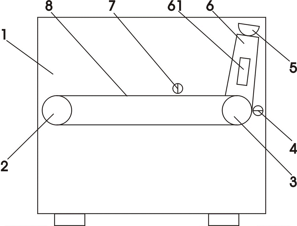
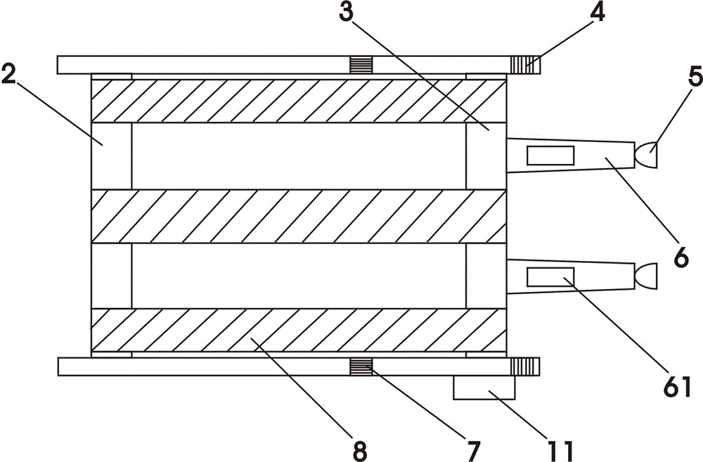
[0008] Now refer to the attached figure 1 And attached figure 2 , combined with specific embodiments as follows: A steel pipe transmission device according to the present invention includes a housing 1, a rotating motor 11, a driven wheel 2, a driving wheel 3, an air suction sensor 4, a vacuum suction cup 5, and a boom 6 , a vacuum generator 61, an inflatable sensor 7 and a transmission belt 8, the housing 1 is the main part of a steel pipe transmission device according to the present invention, an inlet is provided on one side of the housing 1, and one end of the inlet is At the feed end, an outlet is provided on the side opposite to the housing 1, and one end of the outlet is the discharge end, and a driving wheel 3 is arranged at the feeding end, and the driving wheel 3 is perpendicular to the inner surface of the housing 1 , the driving wheel 3 rotates counterclockwise, the driving wheel 3 runs through the inside and outside of the casing 1, a boom 6 is vertically connec...


PUM


Abstract

Disclosed is a steel tube conveying device. The steel tube conveying device comprises a shell, a rotary motor, a driven wheel, a drive wheel, an air exhaust sensor, a vacuum chuck, a hanging arm, a vacuum generator, an air inflation sensor and a conveying belt. When the steel tube conveying device is used, the vacuum chuck at the front end of the hanging arm is driven to perform anticlockwise circular motion under anticlockwise rotation of the drive wheel, and when the vacuum chuck passes through the air exhaust sensor, the vacuum chuck absorbs a steel tube, and then when the vacuum chuck which absorbs the steel tube passes through the air inflation sensor in rotating mode, the steel tube breaks away from the vacuum chuck, and is transported to a stacking place by the conveying belt. The steel tube conveying device is reasonable in design, and simple and convenient to operate, prevents bumping damage generated when the steel tube is directly thrown from a high place, and guarantees completeness of the steel tube to the utmost.

Description

technical field [0001] The invention relates to the field of steel pipe production, in particular to a steel pipe transmission device. Background technique [0002] The transportation and processing of seamless steel pipes generally use a conveyor chain. When the steel pipe is removed from the conveyor chain, it consumes a lot of energy, and the steel pipe falls freely from a certain height. damage or even deformation. Contents of the invention [0003] The object of the present invention is to overcome the disadvantages of the prior art and provide a steel pipe conveying device with reasonable design and easy operation, which can prevent bump damage caused by falling steel pipes. [0004] A steel pipe conveying device according to the present invention includes a housing, a rotating motor, a driven wheel, a driving wheel, an air suction sensor, a vacuum suction cup, a boom, a vacuum generator, an inflating sensor and a transmission belt, and the housing is The main part...

Claims


Application Information

Patent Timeline
Patent Type & Authority Applications(China)
IPC IPC(8): B65G47/91
Inventor 王允星葛凤霞张跃贞李永真
Owner 济宁华奇经贸有限公司
Features
  • Generate Ideas
  • Intellectual Property
  • Life Sciences
  • Materials
  • Tech Scout
  • Unparalleled Data Quality
  • Higher Quality Content
  • 60% Fewer Hallucinations
Learn More