A Multifunctional Hydraulic Buffer Hinge

A hydraulic buffering and multi-functional technology, applied in the hinge field, can solve the problems of door and door frame impact, long working time, loss of buffer closing, etc., and achieve the effects of good sealing performance, long service life and low production cost.

Inactive Publication Date: 2017-04-12
潘约章
View PDF5 Cites 0 Cited by
  • Summary
  • Abstract
  • Description
  • Claims
  • Application Information

AI Technical Summary

Problems solved by technology

When closing the door, sometimes too much force or wind blowing will cause the door and the door frame to collide too loudly or produce a huge impact between the door and the door frame, which may reduce the service life of the door
At present, there are buffer hinge products on the market. Most of the buffer hinges use a direct-push buffer. This buffer needs to be installed on the door, which makes the installation of the buffer hinge complicated and limits its The scope of use, such as plastic steel door frames and other hollow door frames cannot be installed; and a few buffer hinges use rotary dampers, and the rotary dampers have one-way and two-way, to achieve closed door buffer can only use a single One-way damper, the one-way damper of the buffer hinge has a damping effect in the whole door closing stroke, the one-way damper has a longer working time in the door closing stroke, frequent closing of the door will make the one-way The damper is easy to reach the life cycle and loses the effect of buffering and closing the door

Method used


Image

  • A Multifunctional Hydraulic Buffer Hinge
  • A Multifunctional Hydraulic Buffer Hinge
  • A Multifunctional Hydraulic Buffer Hinge

Examples


Embodiment Construction

[0026] The specific implementation manner of the present invention will be further described in detail below in conjunction with the accompanying drawings.

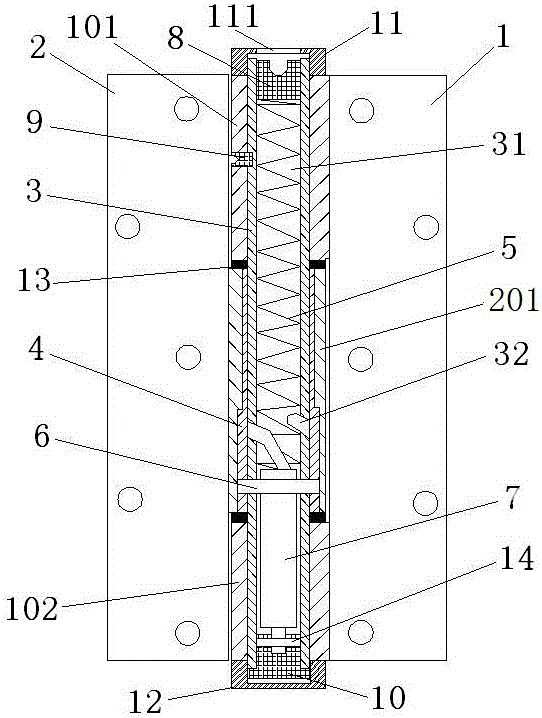
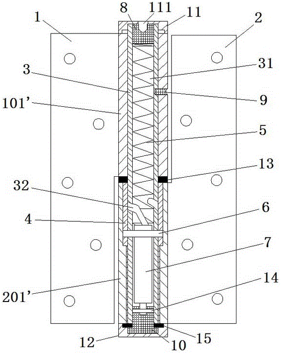
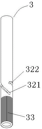
[0027] see in conjunction Figure 1 to Figure 7 As shown, an embodiment of the present invention is a multifunctional hydraulic buffer hinge, which includes a first leaf 1, a second leaf 2 and a shaft core mechanism; the first leaf 1 passes through the shaft core mechanism Rotately connected with the second sheet 2; the shaft core mechanism includes a screw rod 3, a protective sleeve 4, a spring 5, a needle roller 6 and a hydraulic cylinder 7; the screw rod 3 is set in the protective sleeve 4, The screw rod 3 is fixedly connected to the first sheet 1, and the protective cover 4 is fixedly connected to the second sheet 2; the screw rod 3 has a hollow cavity 31, the spring 5 and the hydraulic cylinder 7 are all arranged in the hollow cavity 31, one end of the spring 5 is provided with an adjustment screw 8 for adjusting th...


PUM


Abstract

The invention provides a multifunctional hydraulic buffer hinge. The multifunctional hydraulic buffer hinge comprises a first hinge, a second hinge, a screw rod, a sheath, a spring, a roller pin and a hydraulic oil cylinder, wherein the screw rod is sleeved with the sheath and is fixedly connected with the first hinge, the sheath is fixedly connected with the second hinge, the screw is provided with a hollow cavity, the spring and the hydraulic oil cylinder are arranged in the hollow cavity, one end of the spring is provided with an adjusting screw used for adjusting compression of the spring, the other end of the spring is abutted against the end face of the hydraulic oil cylinder, and the end of a push rod of the hydraulic oil cylinder is fixed on the screw. The outer wall of the screw is provided with a helical slot, the sheath is provided with a rolling slot, and the roller pin is arranged at the end of the hydraulic oil cylinder and penetrates the helical slot and the rolling slot. The multifunctional hydraulic buffer hinge has the advantages of simple structure, low manufacturing cost and long service life and the advantage that functions of automatic door closing by buffering, door stopping positioning, door closing speed and force adjusting are integrated.

Description

technical field [0001] The invention relates to a hinge for opening and closing doors and windows, in particular to a multifunctional hydraulic buffer hinge. Background technique [0002] At present, most of the door hinges are traditional folding hinges, which only have a hinge function and have no buffer function for closing the door. When closing the door, sometimes too much force or wind blowing will cause the door and the door frame to collide too loudly or produce a huge impact between the door and the door frame, which may reduce the service life of the door. At present, there are buffer hinge products on the market. Most buffer hinges use direct-push buffers. This buffer needs to be installed on the door, which makes the installation of the buffer hinge complicated and limits its The scope of use, such as plastic steel door frames and other hollow door frames cannot be installed; and there are a few buffer hinges that use rotary dampers, and the rotary dampers have ...

Claims


Application Information

Patent Timeline
Patent Type & Authority Patents(China)
IPC IPC(8): E05F3/20E05F3/04E05F1/08
Inventor 潘约章
Owner 潘约章
Why Eureka
Try Eureka