Connecting structure of lamp body and lamp pole

A technology of connecting structure and lamp body, which is applied to the parts of lighting devices, lighting devices, outdoor lighting, etc., can solve the problems of affecting stability, not long service life, and poor use effect of the installation tube at the rear of the street lamp, and achieves high reliability. The effect of stable force and improved impact resistance

Active Publication Date: 2015-09-09
ZHEJIANG JINGRI LIGHTING TECH
View PDF6 Cites 2 Cited by
  • Summary
  • Abstract
  • Description
  • Claims
  • Application Information

AI Technical Summary

Problems solved by technology

However, because the connecting shaft rotates in the circumferential direction, it will affect the stability of the rack and the tooth groove after the alignment and engagement. When the lamp is subjected to external impact force, coupled with the gravity of the lamp body itself, the installation tube at the end of the street lamp will not work well. , the service life is not long
In addition, when installing and maintaining the existing connection structure between the lamp body and the lamp pole, it is necessary to open the lamp body shell for operation, which is inconvenient to operate

Method used


Image

  • Connecting structure of lamp body and lamp pole
  • Connecting structure of lamp body and lamp pole
  • Connecting structure of lamp body and lamp pole

Examples


Embodiment Construction

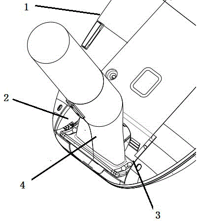
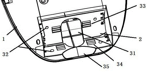
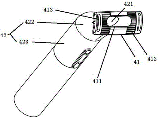
[0021] Such as Figure 1-3 , The connecting structure of the lamp body and the lamp pole of the present invention includes a concave portion 2, a connecting base 3, and a connecting rod 4. The concave portion 2 is provided on the outside of the lamp body 1, for example, on the front of the lamp body 1, that is, the side facing the ground, the connecting base 3 is provided in the concave portion 2, and the connecting rod 4 is connected to the The base 3 is connected in an adjustable angle. This arrangement hides the structure of the connecting base 3, which is beneficial to the appearance of the lamp body. At the same time, the connecting rod 4 interacts with the connecting base 3, and the force is applied to the connecting base 3, that is, to the lamp body 1. The above is beneficial to the stable connection between the connecting rod 4 and the connecting base 3. In addition, it is also convenient for the operator to install and adjust the angle of the lamp body.

[0022] The c...


PUM


Abstract

The invention provides a connecting structure of a lamp body and a lamp pole, and belongs to the technical field of lamps. The connecting structure comprises a concave part arranged at the outer side of the lamp body, a connecting substrate arranged in the concave part, and a connecting rod in connection with the connecting substrate in a manner of angle modulation; the connecting substrate comprises a through hole communicated with the lamp body, a fixing part, and a first positioning part and a second positioning part matched with the fixing part for realizing connection of different positions between the connecting rod and the connecting substrate; the connecting rod comprises a mounting part and a supporting part; the supporting part of the connecting rod is provided with a cable cavity communicated with the through hole of the lamp body; the first positioning part and the second positioning part are arranged on two mounting surfaces of the connecting substrate; the mounting part can be matched with the first positioning part or the second positioning part so as to ensure that the lamp body and the lamp pole can be horizontally or vertically connected. Horizontal connection or vertical connection of the lamp body and the lamp pole can be adjusted at the outer side of the lamp body, or the angle between the connecting substrate and the connecting rod can be adjusted at the outer side of the lamp body, so that operators can conveniently perform mounting and maintenance, the adjusting precision is higher, and the firmness and the stability are better.

Description

Technical field [0001] The invention relates to the technical field of lamps, in particular to a connection structure between a lamp body and a lamp pole. Background technique [0002] At present, lamps and lanterns widely used in cities, such as street lamps, are generally fixedly connected to the lamp post by welding during installation. Once the installation is completed, the installation angle between the lamp body and the lamp post is fixed and cannot be adjusted , Which makes the actual use process quite inconvenient, and the light output effect cannot meet the actual road conditions. In the prior art, a single-row pair of teeth adjustment mechanism is used to adjust the angle between the lamp body and the lamp pole. Although the problem of non-adjustable angle is solved, the rack needs to withstand greater force, the rack is easily damaged and has a short service life. Lead to poor adjustment accuracy. The utility model ZL200920305958.6 discloses a street lamp ta...

Claims


Application Information

Patent Timeline
IPC IPC(8): F21V19/00F21V19/02F21W131/103
CPCF21V19/00F21V19/0025F21V19/0055F21V19/02F21W2131/103
Inventor 丁菲菲崔喆叶少军
Owner ZHEJIANG JINGRI LIGHTING TECH
Why Eureka
Try Eureka