Switch drive method based on universal model

A driving method and a general-purpose model technology, applied in the direction of program control devices, etc., can solve problems such as inability to drive various switch structures

Active Publication Date: 2015-09-09
HARBIN INST OF TECH
View PDF3 Cites 2 Cited by
  • Summary
  • Abstract
  • Description
  • Claims
  • Application Information

AI Technical Summary

Problems solved by technology

[0006] The present invention is to solve the problem that the existing switch driving module cannot drive various switch structures, and the present invention provides a Switch driving method based on a general model

Method used


Image

  • Switch drive method based on universal model
  • Switch drive method based on universal model
  • Switch drive method based on universal model

Examples


specific Embodiment approach 1

[0044] Specific implementation mode one: the Switch driving method based on the general matrix model described in this implementation mode, the specific process of this method is:

[0045] Step 1, the establishment of a general matrix model;

[0046] Step 2, realize the driving of Switch by using the established general matrix model.

specific Embodiment approach 2

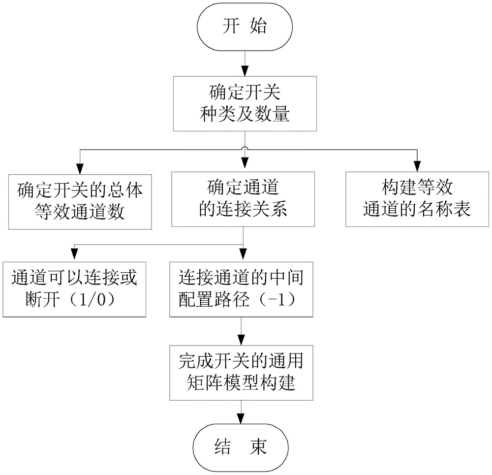
[0047] Specific implementation mode two: see figure 1 Describe this embodiment, the difference between this embodiment and the switch driving method based on the general matrix model described in the specific embodiment one is that in step one, the specific process of establishing the general matrix model is:

[0048] Step one, determine the type and quantity of the switch,

[0049] Steps 1 and 2, let each end of each switch be a channel, get the number of channels of all switches according to the type and quantity of the switch, determine the connection relationship of each channel, and name all the channels, so as to construct the equivalent channel name Table, all the named channels are used as the row items and column items of the equivalent channel name table respectively, the space surrounded by the row items and column items of the equivalent channel name table constitutes a model matrix, and the number of channels of all switches is equal to The dimensions of the mode...

specific Embodiment approach 3

[0053] Specific embodiment three: the difference between this embodiment and the switch driving method based on the general matrix model described in specific embodiment two is that it also includes steps one and three,

[0054] Step 13 is to establish an equivalent channel name index table according to the equivalent channel name table in step 12. The equivalent channel name index table reflects the name of each channel and the corresponding index number of each channel. By calling the equivalent channel The name index table completes the call to the general matrix model.

[0055] In this embodiment, this method establishes a name index list for equivalent channels. The establishment of this index table is convenient for the user to configure the driver program and quickly realize path retrieval, and facilitates the system expansion of the program.


PUM


Abstract

A Switch drive method based on a universal model belongs to the field of constructing Switch universal models, so as to solve the problems that the existing switch drive modules cannot drive multiple switch structures. The method comprises the following steps: step 1-1, determining the variety and the quantity of switches; step 1-2, allowing each end of each switch to be a channel; obtaining the channel number of all the switches based on the variety and the quantity of the switches; determining connection relationships among each channel, and naming all the channels for constructing an equivalent channel name list; using all the named channels respectively as row items and column items of the equivalent channel name list; constructing a model matrix by the space encircled by the row items and the column items of the equivalent channel name list; filling corresponding values in the model matrix based on the connection relationships among each channel, thereby finishing establishing the universal matrix model; step 2, driving the Switch by using the established universal matrix model. The Switch drive method based on the universal model is used for driving the switches.

Description

technical field [0001] The invention belongs to the construction field of Switch universal model. Background technique [0002] Crossbar switch (Switch) is widely used in various test instruments and test systems. The switch is a bridge connecting the control system and the unit under test. It is an important interface part of the entire test system. The use of each Switch switch requires Corresponding driver development program. [0003] However, the conventional driver development program has the following two problems: 1) For testers, for different Switch crossbar modules, different test programs need to be written to complete the use of different switch modules; 2) For instrument developers That is to say, the same Switch module needs to provide different drivers for different development environments. For example, if users use VC development environment to develop test systems, instrument manufacturers need to provide drivers for VC development environments, and users ...

Claims


Application Information

Patent Timeline
Patent Type & Authority Applications(China)
IPC IPC(8): G06F9/44
Inventor 崔秀海马云彤杨爽王晓龙彭宇彭喜元
Owner HARBIN INST OF TECH
Why Eureka
Try Eureka