AI technical title is built by Patsnap AI team. It summarizes the technical point description of the patent document.
A driving method and model technology, applied in the direction of creating/generating source code, etc., can solve the problem of not being able to drive a variety of switch structures
Active Publication Date: 2018-03-16
HARBIN INST OF TECH
View PDF3 Cites 0 Cited by
Summary
Abstract
Description
Claims
Application Information
AI Technical Summary
This helps you quickly interpret patents by identifying the three key elements:
Problems solved by technology
Method used
Benefits of technology
Problems solved by technology
[0006] The present invention is to solve the problem that the existing switch driving module cannot drive various switch structures, and the present invention provides a Switch driving method based on a general model
Method used
Image
Click on the blue label to locate the original text in one second.
Reading with bidirectional positioning of images and text.
Examples
specific Embodiment approach 1
[0043] Embodiment 1: The Switch driving method based on the general matrix model described in this embodiment, the specific process of the method is:
[0044] Step 1, the establishment of a general matrix model;
[0045] The second step is to realize the driving of the Switch by using the established general matrix model.
specific Embodiment approach 2
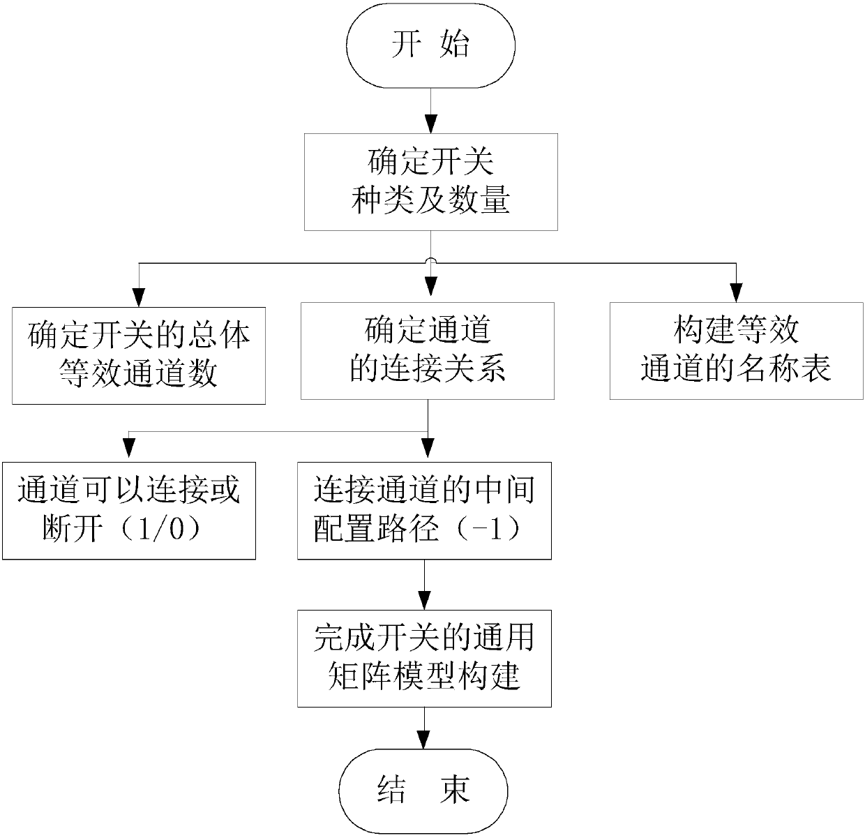
[0046] Specific implementation two: see figure 1 Explain this embodiment, the difference between this embodiment and the Switch driving method based on the general matrix model described in the specific embodiment 1 is that in step 1, the specific process of establishing the general matrix model is:
[0047] Step 11, determine the type and quantity of switches,
[0048] Steps 1 and 2, make each end of each switch a channel, obtain the number of channels of all switches according to the type and number of switches, determine the connection relationship of each channel, and name all channels to construct equivalent channel names Table, take all the named channels as row items and column items of the equivalent channel name table respectively, and the space enclosed by the row items and column items of the equivalent channel name table constitutes a model matrix, and the number of channels of all switches is the same as The dimensions of the model matrix are the same,
[0049] ...
specific Embodiment approach 3
[0052] Embodiment 3: The difference between this embodiment and the general matrix model-based Switch driving method described in Embodiment 2 is that it further includes steps 1 and 3,
[0053] Steps 1 and 3 are to establish an equivalent channel name index table according to the equivalent channel name table in steps 1 and 2. The equivalent channel name index table reflects the name of each channel and the index number corresponding to each channel, and the equivalent channel is called by calling the equivalent channel. The name index table completes the call to the generic matrix model.
[0054] In this embodiment, the method establishes a name index list for the equivalent channels, and the establishment of the index table is convenient for the user to configure the driver and quickly realize the path retrieval, and facilitates the system expansion of the program.
PUM
Abstract
The Switch driving method based on the general model belongs to the construction field of the general model of Switch. In order to solve the problem that the existing switch driving module cannot drive various switch structures. Step 11, determine the type and quantity of switches, step 12, make each end of each switch a channel, obtain the channel numbers of all switches according to the type and quantity of switches, determine the connection relationship of each channel, and The channels are named, so as to construct the equivalent channel name table, and all the named channels are respectively used as the row items and column items of the equivalent channel name table, which are surrounded by the row items and column items of the equivalent channel name table The space constitutes the model matrix, and fills in the corresponding values in the model matrix according to the connection relationship of each channel, so as to complete the establishment of the general matrix model. Step 2 is to realize the driving of the Switch by using the established general matrix model. It is used to drive the switch.
Description
technical field [0001] The invention belongs to the field of constructing a general model of Switch. Background technique [0002] Cross switch (Switch) is widely used in various test instruments and test systems. The switch is a bridge connecting the control system and the unit under test, and is an important interface part of the entire test system. The use of each switch requires The corresponding driver development program. [0003] However, the conventional driver development program has the following two problems: 1) For testers, for different Switch crossbar switch modules, different test programs need to be written to complete the use of different switch modules; 2) For instrument developers to It is said that the same Switch module needs to provide different drivers for different development environments. For example, if the user uses the VC development environment to develop the test system, the instrument manufacturer needs to provide the driver for the VC develo...
Claims
Application Information
Patent Timeline
Application Date:The date an application was filed.
Publication Date:The date a patent or application was officially published.
First Publication Date:The earliest publication date of a patent with the same application number.
Issue Date:Publication date of the patent grant document.
PCT Entry Date:The Entry date of PCT National Phase.
Estimated Expiry Date:The statutory expiry date of a patent right according to the Patent Law, and it is the longest term of protection that the patent right can achieve without the termination of the patent right due to other reasons(Term extension factor has been taken into account ).
Invalid Date:Actual expiry date is based on effective date or publication date of legal transaction data of invalid patent.

