
Front-mounted straw returning machine

A front-mounted, straw technology, applied in the field of machinery, can solve the problems of affecting the use effect and the failure of the straw returning machine to process, and achieve a highly convenient and easy-to-use effect

Active Publication Date: 2017-01-18
HENAN KAINONG MACHINERY
View PDF9 Cites 0 Cited by
  • Summary
  • Abstract
  • Description
  • Claims
  • Application Information

AI Technical Summary

Problems solved by technology

[0002] The straw returning machine has a frame, and there are connecting parts on the frame. The connecting parts refer to the parts connected with the traction device; in the prior art, the straw returning machine is installed behind the traction device, that is, Said that the connecting parts are set in front of the frame, such a straw returning machine often returns the straw after being crushed by the tractor, and the straw returning machine cannot process it due to the straw being dumped, which affects the use Effect

Method used


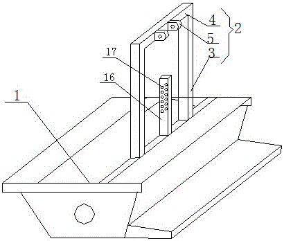
Image

  • Front-mounted straw returning machine
  • Front-mounted straw returning machine
  • Front-mounted straw returning machine

Examples


Embodiment Construction

[0014] The present invention will be further described below in conjunction with the accompanying drawings.

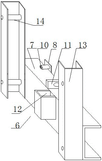
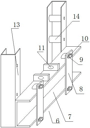
[0015] Such as figure 1 , 2 As shown in .

[0016] Like this, the present invention can be installed in the front of traction device such as tractor, can satisfy some farming requirements.

[0017] Further, the connecting part is that there are two vertical rectangular tubes 3 on the frame, and a beam 4 is arranged above the rectangular tubes, the rectangular tubes and the beams form a frame, and there are also height-adjustable ears on the frame. Sheet 5, hydraulic cylinder 15 is installed below the ear sheet.

[0018] This requires that the front of the traction device has an installation structure that cooperates with the frame body, and cooperates with the installation.

[0019] Further, it also includes a mounting frame 6, and the mounting frame includes a first channel steel 7 with an opening facing rearward and arranged laterally, with first screw holes on b...


PUM


Abstract

The invention relates to the technical field of machinery, and discloses a preposed straw returning machine, which comprises a straw returning machine body, wherein the straw returning machine body comprises a rack; a connecting part is arranged on the rear part of the rack, and comprises two rectangular pipes arranged on the rack; a beam is arranged on the rectangular pipes; the rectangular pipes and the beam form a frame; height regulation lugs are further arranged on the frame; a hydraulic cylinder is arranged below the lugs. The preposed straw returning machine further comprises a mounting frame, wherein the mounting frame comprises a piece of first channel steel which has a backward opening and is transversely arranged; first screw holes are formed in the two sides of the upper and lower parts of the first channel steel; fixed plates are further arranged behind the first channel steel; second screw holes are formed in the two ends of the fixed plates; the first screw holes correspond to the second screw holes, and are connected with the second screw holes through screws; a connecting part of the hydraulic cylinder, the hydraulic cylinder and the like are arranged on the first channel steel. The preposed straw returning machine has the advantages of convenience in use and capability of meeting certain production requirements.

Description

technical field [0001] The invention relates to the technical field of machinery, in particular to a straw returning machine. Background technique [0002] The straw returning machine has a frame, and there are connecting parts on the frame. The connecting parts refer to the parts connected with the traction device; in the prior art, the straw returning machine is installed behind the traction device, that is, Said that the connecting parts are set in front of the frame, such a straw returning machine often returns the straw after being crushed by the tractor, and the straw returning machine cannot process it due to the straw being dumped, which affects the use Effect. Contents of the invention [0003] The object of the present invention is to solve the above-mentioned shortcomings, and provide a straw returning machine that does not return to the field after being caused by rolling, resulting in poor use effect—a front-mounted straw returning machine. [0004] The tech...

Claims


Application Information

Patent Timeline
Patent Type & Authority Patents(China)
IPC IPC(8): A01D82/00
Inventor 盛庆军
Owner HENAN KAINONG MACHINERY
Learn More