Laser marking machine switching valve

A technology of laser coding machine and valve opening and closing, which is used in printing and other directions to achieve the effect of broadening the application field

Inactive Publication Date: 2015-09-16
王丽
View PDF7 Cites 0 Cited by
  • Summary
  • Abstract
  • Description
  • Claims
  • Application Information

AI Technical Summary

Problems solved by technology

[0002] In the current era when laser marking is popular, laser coding machines have been widely promoted and applied in various fields. The switch valve of laser coding machines currently used has defects in adjusting the laser flow rate.

Method used


Image

  • Laser marking machine switching valve
  • Laser marking machine switching valve

Examples


Embodiment Construction

[0012] The preferred embodiments of the present invention will be described in detail below in conjunction with the accompanying drawings, so that the advantages and features of the present invention can be more easily understood by those skilled in the art, so as to define the protection scope of the present invention more clearly.

[0013] The invention provides a widening field and a moderately adjustable switch valve for a laser coding machine.

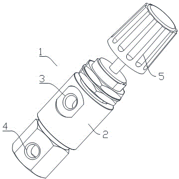
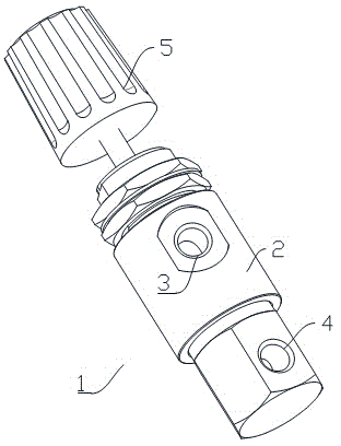
[0014] Such as figure 1 , figure 2 As shown, a switch valve 1 of a laser coding machine includes a conductor 2, a first round hole 3 and a second round hole 4 are opened on the conductor 2, and a Nut knob 5.

[0015] Such as figure 1 , figure 2 As shown, the outer layer of the conductor 2 is covered with a thermal insulator.

[0016] Such as figure 1 , figure 2 As shown, the nut knob 5 has anti-slip threads.

[0017] The laser coding machine of the invention is provided with a conductor on the body, two circular holes a...


PUM


Abstract

The invention discloses a laser marking machine switching valve. The laser marking machine switching valve comprises a conductor; a first circular hole and a second circular hole are formed in the conductor; one end of the conductor is fixedly connected with one nut knob; the outer layer of the conductor is covered with a thermal isolation insulating body; and the nut knob is provided with an antiskid screw thread. According to the laser marking machine switching valve of the invention, the conductor is arranged on the body of a laser marking machine; the two circular holes are formed in the conductor; one end of the conductor is fixedly connected with the nut knob; the surface of the conductor is covered with the thermal isolation insulating body; the nut knob is provided with the antiskid screw thread; and therefore, the nut knob can be utilized to control the size of the first circular hole and the second circular hole in the conductor of the switching valve, so that laser flow rate can be adjusted, and thus, the application field of the laser marking machine can be expanded.

Description

technical field [0001] The invention relates to a switching valve, more precisely, a laser coding machine switching valve. Background technique [0002] In the current era when laser marking is popular, laser coding machines have been widely promoted and applied in various fields. The switch valve of laser coding machines currently used has defects in adjusting the laser flow rate. Contents of the invention [0003] The present invention mainly solves the technical problems existing in the prior art, thereby providing a switch valve for a laser marking machine that can broaden the field and be moderately adjusted. [0004] Above-mentioned technical problem of the present invention is mainly solved by following technical scheme: [0005] A switch valve for a laser marking machine includes a conductor, a first round hole and a second round hole are opened on the conductor, and a nut knob is fixedly connected to one end of the conductor. [0006] As a preferred embodiment o...

Claims


Application Information

Patent Timeline
IPC IPC(8): B41J2/435
Inventor 王丽
Owner 王丽
Why Eureka
Try Eureka