Eureka AIR delivers breakthrough ideas for toughest innovation challenges, trusted by R&D personnel around the world.

Microelectromechanical heating apparatus and fluid preconcentrator device utilizing same

a technology of micro-electromechanical heating and fluid preconcentration, which is applied in the direction of lighting, heating apparatus, furniture, etc., can solve the problems of large size/weight, limited power requirements, and limited application of traditional gc instruments, so as to increase the porosity of heating elements, reduce the width of heating elements, and increase the surface area

Inactive Publication Date: 2005-07-05
RGT UNIV OF MICHIGAN
View PDF18 Cites 78 Cited by
  • Summary
  • Abstract
  • Description
  • Claims
  • Application Information

AI Technical Summary

Benefits of technology

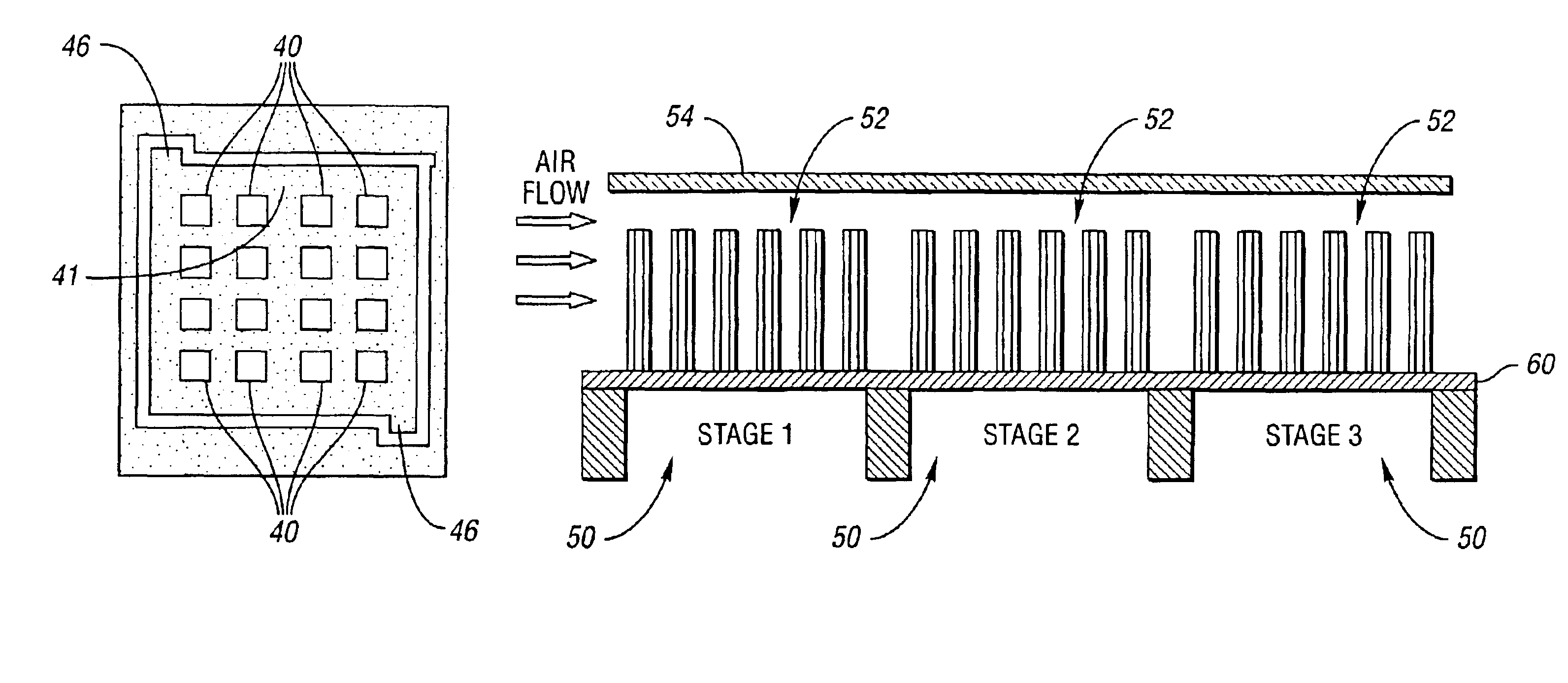
[0033]The microsensing system may serve as a 3D micro chemical sensing system. The apparatus may further comprise sensing material applied to large surface area of the heating elements for improved sensitivity and response time and sensing electrodes distributed along a surface of the heating apparatus for 3D detection of chemical distribution.
[0042]The device may further include tubes sealingly disposed within the inlet and the outlet. The tubes may have low thermal conductivity to minimize conductive heat loss to structures external to the at least one heating chamber.
[0051]A width of the heating elements may be reduced to the nanometer range. The at least one heater may be a nanoheater which provides larger surface area per unit volume compared to a microheater. The size of the nanoheater may be smaller than a microheater for the same surface area, and has a smaller thermal mass. The nanoheater may have a lower power consumption and faster thermal response than a microheater.

Problems solved by technology

Traditional GC instrumentation is large and requires high power.
Field portable instruments have been developed for environmental, clinical, aerospace, process control, and other applications, but remain limited by their size / weight (several kg) and power requirements (tens-to-hundreds of W).
Capillary tubes suffer from large dead volume and limited heating efficiency due to their larger thermal mass.
Although rapid thermal desorption at relatively low power can be achieved with such structures, the capacity of the PCF is very low and therefore not suitable for quantitative analysis of multi-vapor mixtures.

Method used


Image

  • Microelectromechanical heating apparatus and fluid preconcentrator device utilizing same
  • Microelectromechanical heating apparatus and fluid preconcentrator device utilizing same
  • Microelectromechanical heating apparatus and fluid preconcentrator device utilizing same

Examples


Embodiment Construction

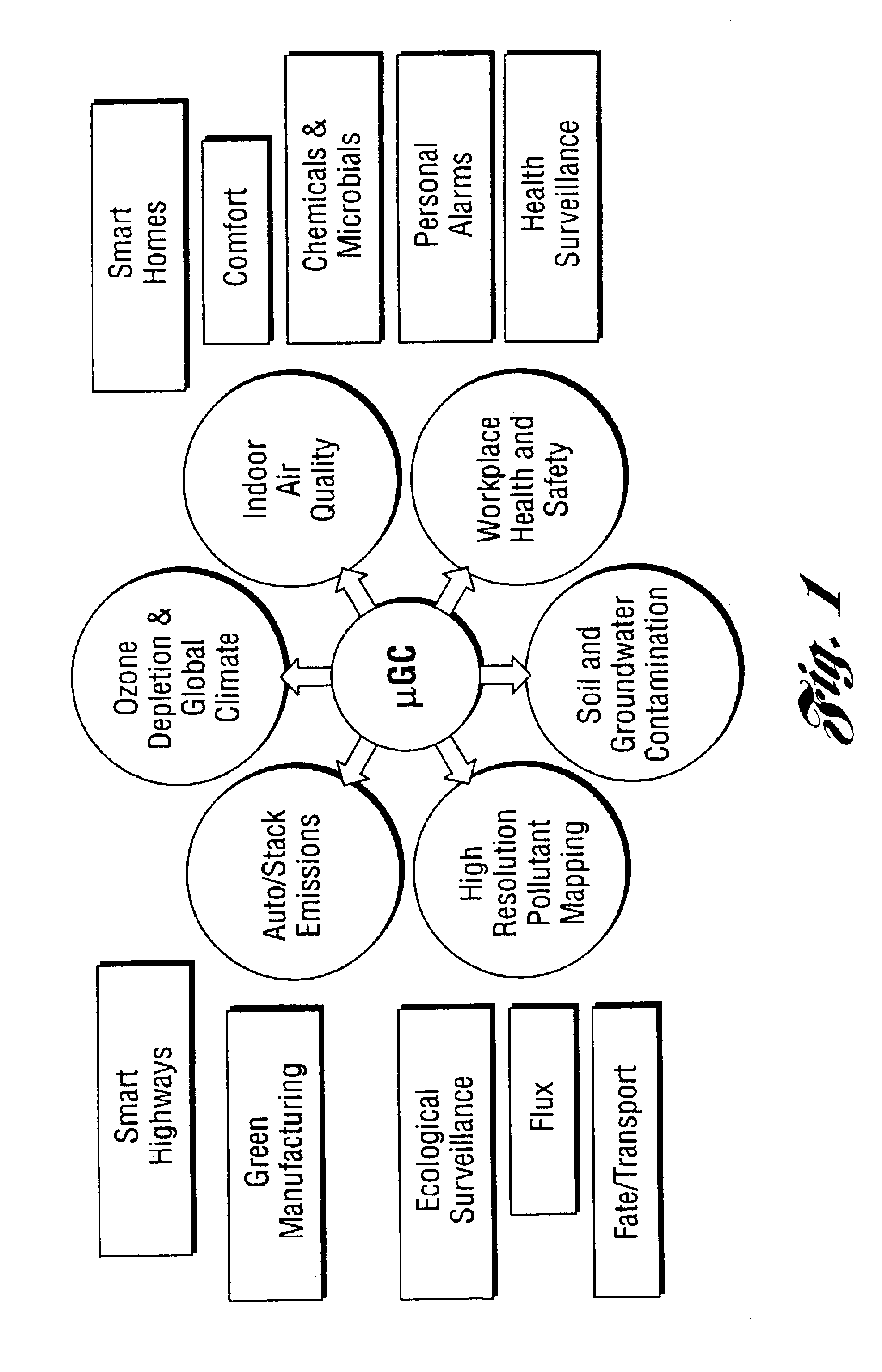
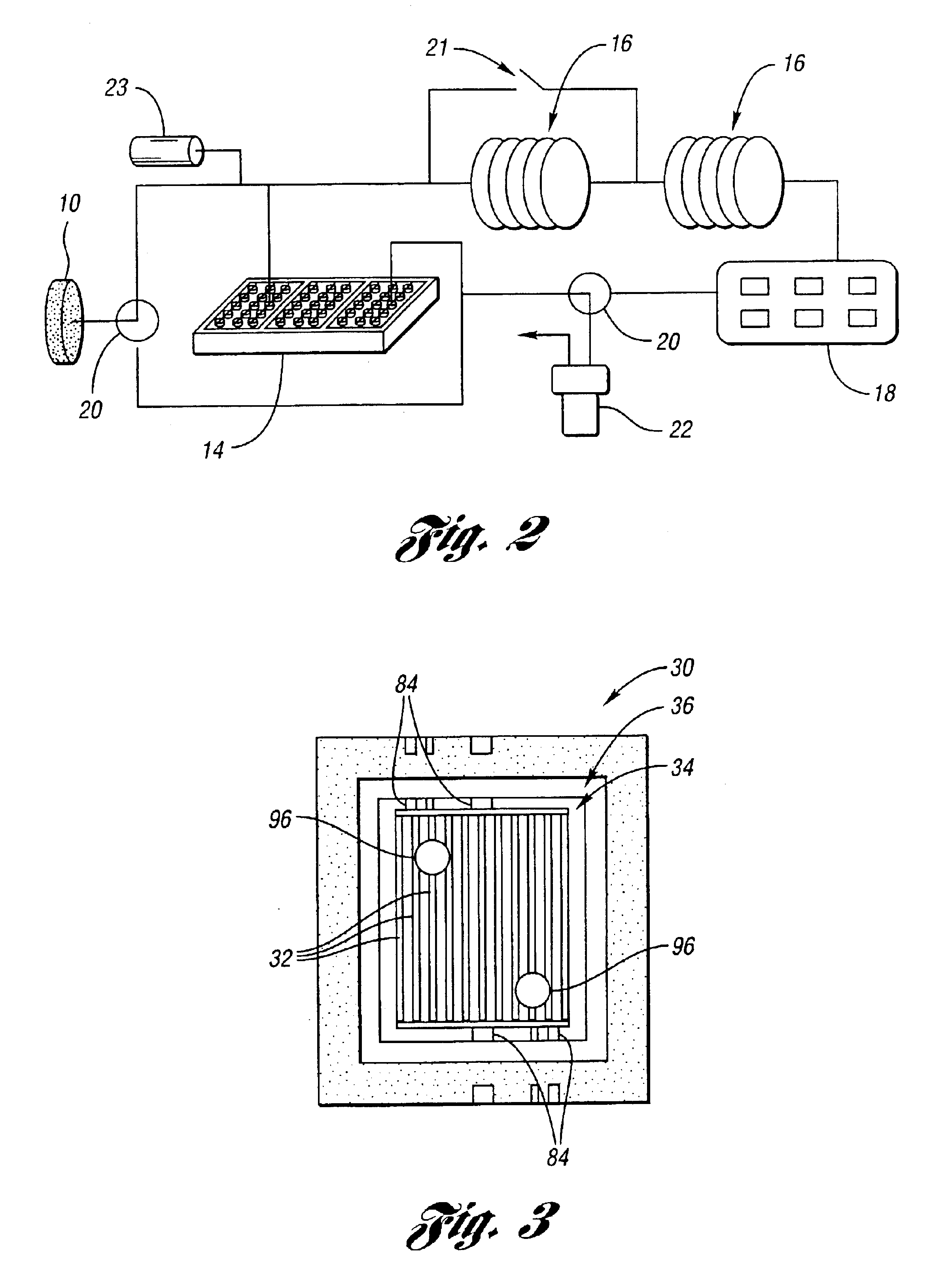
[0063]The present invention relates generally to a micro analytical system and, in particular, to a high aspect ratio microheater, with tall and large surface area heating elements or structures, for a microfabricated preconcentrator / focuser (μPCF). This high aspect ratio bulk-micromachined Si heater can be packed in an embodiment with a small quantity of adsorbent material to form a μPCF. It is designed to preconcentrate vapors for subsequent focused thermal desorption and chemical analysis in a micro gas chromatograph (μGC). Previous efforts on miniaturizing PCFs have focused on thin heated membranes coated with adsorbents. However, they are limited in achieving high sensitivity and quantitative analysis due to small adsorbent capacity. Besides, as the adsorbent layer thickness is increased to reach sufficient capacity, the thermal transfer efficiency from the thin heater on the membrane decreases dramatically, calling for alternative heater designs. By using the μPCF of the prese...


PUM


Abstract

A microelectromechanical heating apparatus and fluid preconcentrator device utilizing same wherein heating elements of the apparatus are sized and spaced to substantially uniformly heat a heating chamber within a heater of the apparatus. Tall, thermally-isolated heating elements are fabricated in Si using high aspect ratio etching technology. These tall heating elements have large surface area to provide large adsorbent capacity needed for high efficiency preconcentrators in a micro gas chromatography system (μGC). The tall heating elements are surrounded by air gaps to provide good thermal isolation, which is important for a low power preconcentrator in the μGC system.

Description

CROSS-REFERENCE TO RELATED APPLICATION[0001]This application claims the benefit of U.S. provisional application Ser. No. 60 / 413,026, filed Sep. 24, 2002.STATEMENT REGARDING FEDERALLY SPONSORED RESEARCH OR DEVELOPMENT[0002]This invention was made with Government support under Contract No. ERC-998 6866 awarded by the National Science Foundation. The Government has certain rights to the invention.BACKGROUND OF THE INVENTION[0003]1. Field of the Invention[0004]This invention relates to a microelectromechanical heating apparatus and fluid preconcentrator devices utilizing same.[0005]2. Background Art[0006]Researchers have fabricated microheaters using thin metal as shown in references [1]-[12], poly-Si as shown in references [13]-[21], or Si as shown in references [22]-[23] on dielectric membranes with lower thermal mass for chemical sensing and other applications. The ratio of height to width of some prior art microheaters is generally smaller than 1. The range of the ratio is around 1e...

Claims


Application Information

Patent Timeline
Patent Type & Authority Patents(United States)
IPC IPC(8): F27D11/00F27B17/00H05B3/26
CPCF27B17/0025H05B3/26H05B2203/003H05B2203/005H05B2203/007H05B2203/013H05B2203/017
Inventor TIAN, WEI-CHENGPANG, STELLA W.ZELLERS, EDWARD T.
Owner RGT UNIV OF MICHIGAN
Why Eureka
Eureka Blog
Learn More