

Mechanical sealing structure of gas lubricating end face with human pyramid-like combined groove deep grooves
A technology of end face mechanical seal and sealing structure, which is applied in the direction of engine sealing, mechanical equipment, engine components, etc., can solve the problems of insufficient air film stiffness, high air film stiffness, and low leakage rate, etc., to reduce the eddy current effect and improve Effect of bearing capacity and air film stiffness, strong pumping action
- Summary
- Abstract
- Description
- Claims
- Application Information
AI Technical Summary
Problems solved by technology
Method used
Image

Examples
Embodiment 1
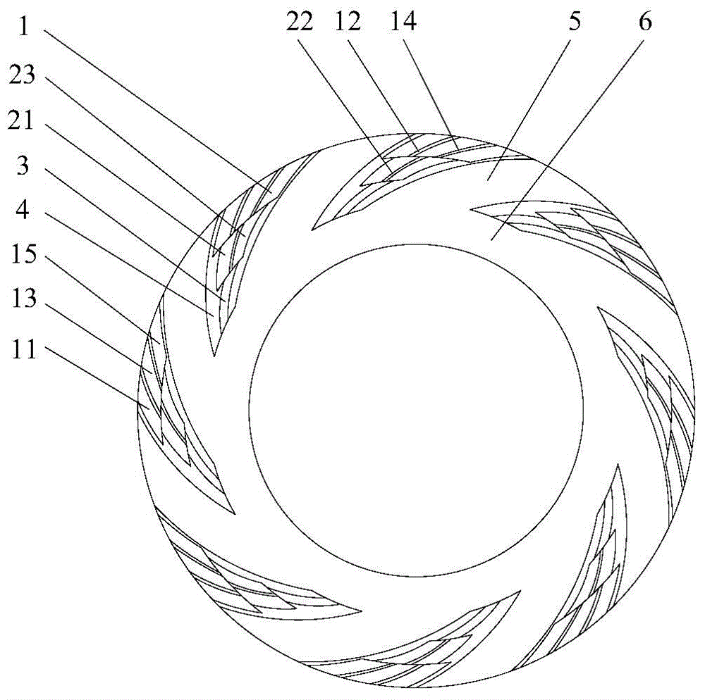
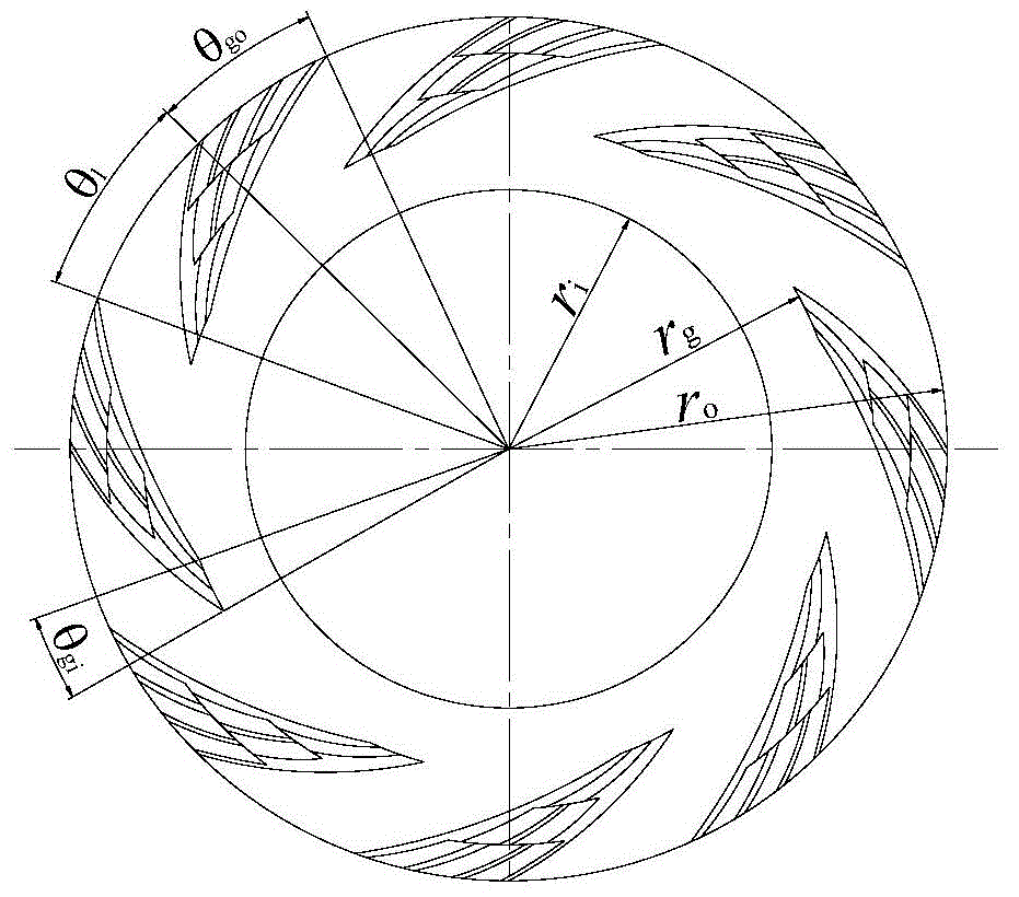
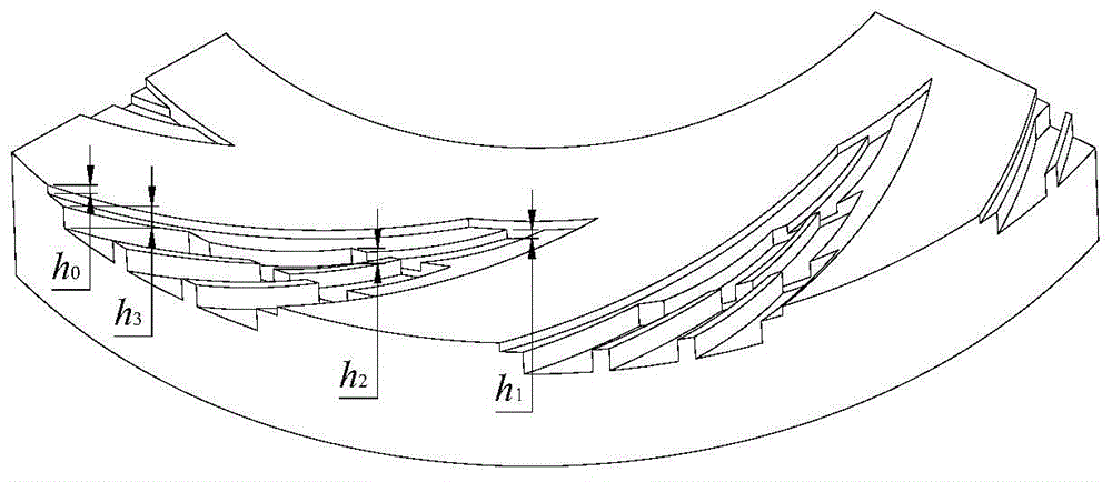
[0033] see figure 1 , figure 2 and image 3, a mechanical seal structure with gas lubricated end faces of deep grooves similar to stacked Arhat composite grooves, including a dynamic ring and a static ring of a mechanical seal. The other side of the end face of the ring is the low-pressure side, that is, the downstream side, which is characterized in that: the end face of at least one seal ring in the moving ring and the static ring is provided with a plurality of deep grooves that are evenly distributed along the circumferential direction, resembling composite grooves of arhats. The deep-groove like stacked Arhat compound groove is composed of basic dynamic pressure groove 4 and stacked Arhat-shaped groove 1, the basic dynamic pressure groove 4 is opened upstream of the end face, and the bottom surface of the basic dynamic pressure groove 4 is processed with a stacked Arhat-like groove. Groove 1, the upstream sub-grooves 11, 13 and 15 of the adjacent two rows of grooves in...
Embodiment 2
[0040] refer to Figure 5 and Figure 6 The difference between this embodiment and Embodiment 1 is that in the arhat-like groove, the sub-groove on the downstream side and the sub-groove on both sides of the sealing weir on the upstream side straddled by the base The fan-shaped sealing weirs with the same depth of dynamic pressure grooves are separated.
[0041] The sub-grooves 11, 13, 15 in the upstream row are separated from the sub-grooves 21, 23 in the adjacent downstream row by a sealing dam 42 that is equal in depth to the foundation dynamic pressure groove 4, and the sub-grooves 21, 23 in the middle row are separated from the adjacent sub-grooves. The downstream row sub-grooves 3 are separated by a sealing dam 41 whose depth is equal to that of the basic dynamic pressure groove 4, and the rest of the structure and implementation are the same as in the first embodiment.
Embodiment 3
[0043] refer to Figure 7 and Figure 8 , the difference between this embodiment and Embodiment 1 is that the sub-slots 21 and 23 of the middle row are respectively embedded between the adjacent upstream row of sub-slots 11 and 13 and 13 and 15, and the downstream row of sub-slots 3 It is embedded between the sub-slots 21 and 23 in the middle row, and the rest of the structure and implementation are the same as in the first embodiment.
PUM
 Abstract
Description
Claims
Application Information