
A current limiting method and a current limiting device

A current limiting method and a technology of a current limiting device, which are applied in the direction of output power conversion devices, electrical components, single-network parallel feeding arrangement, etc., can solve potential safety hazards, photovoltaic inverter overcurrent protection photovoltaic inverter damage, Unable to realize non-off-network operation and other problems

Active Publication Date: 2017-11-07
深圳市英威腾光伏科技有限公司
View PDF6 Cites 0 Cited by
  • Summary
  • Abstract
  • Description
  • Claims
  • Application Information

AI Technical Summary

Problems solved by technology

[0002] The instantaneous inrush current in the photovoltaic inverter power generation and grid connection brings great safety hazards to the power electronic switch in the photovoltaic inverter and the entire photovoltaic system, and even causes the photovoltaic inverter overcurrent protection or the photovoltaic inverter damage to
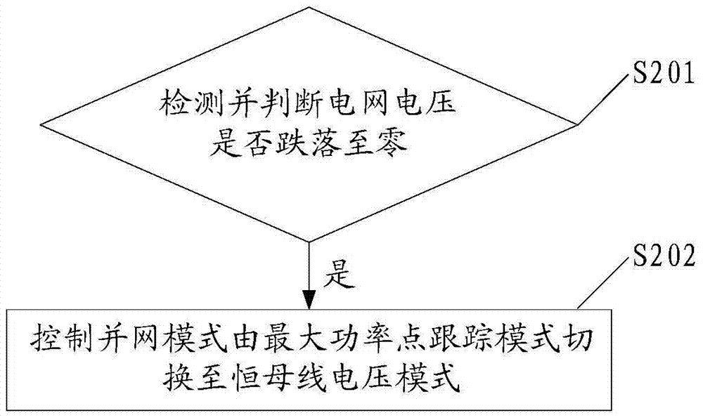
Especially in low voltage ride through, when the voltage of the three-phase grid drops to the preset value and the most serious fault occurs, the photovoltaic inverter has no time to smoothly transmit the energy accumulated on the DC side to the grid, resulting in three-phase output of the photovoltaic inverter. The phase current has a large inrush current or oscillation; and when the three-phase grid voltage recovers instantly, due to the output error of the phase-locked loop, etc., the photovoltaic inverter may still output a large inrush current. Once the photovoltaic inverter current protection threshold is exceeded If it is disconnected from the power grid, the basic technical index of non-off-grid operation during low voltage ride-through cannot be achieved, that is, low-voltage ride-through failure
[0003] In addition, in the working process of other inverters, there is often a lack of effective protection against inrush current. Therefore, it is necessary to provide a current limiting method suitable for the entire operation process of the inverter.

Method used


Image

  • A current limiting method and a current limiting device
  • A current limiting method and a current limiting device
  • A current limiting method and a current limiting device

Examples


Embodiment Construction

[0032] The following will clearly and completely describe the technical solutions in the embodiments of the present invention with reference to the accompanying drawings in the embodiments of the present invention. Obviously, the described embodiments are only some, not all, embodiments of the present invention. Based on the embodiments of the present invention, all other embodiments obtained by persons of ordinary skill in the art without making creative efforts belong to the protection scope of the present invention.

[0033] The present invention provides a current limiting method, which is applied to inverters, and the inverters may specifically be photovoltaic inverters, UPS (Uninterruptible Power System, uninterruptible power supply) or power inverters, etc., to solve current problems. Some technologies lack the protection of inverters in the face of inrush current during grid connection.

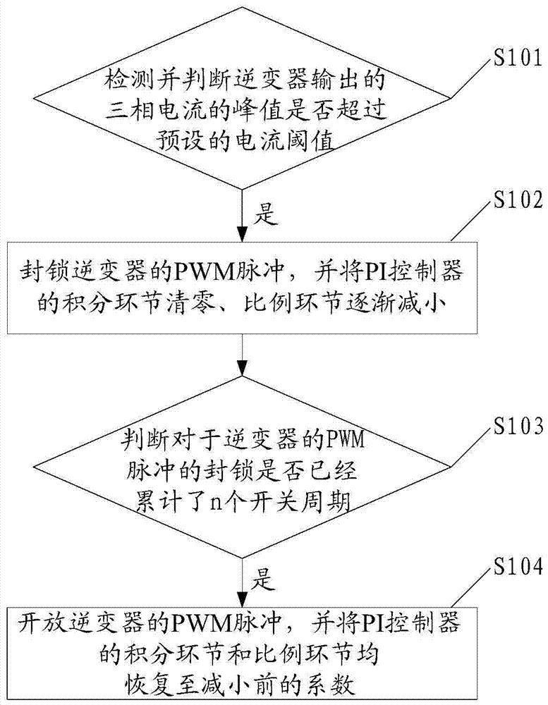
[0034] Specifically, the current limiting method, such as figure 1 shown, includ...


PUM


Abstract

The present invention discloses a current limiting method and a current limiting apparatus. The method comprises: detecting, by using the control system of an inverter, three-phase current output by the inverter, blocking PWM pulse of the inverter when it is detected that the peak of any phase current in the three-phase current exceeds the preset current threshold, clearing the integral element of the PI controller, and gradually reducing the proportion element of the PWM controller; and when it is judged that the locking of the PWM pulse of the inverter has accumulated N switch cycles, opening the PWM pulse of the inverter and gradually restore the proportion element of the PI controller to the coefficient prior to the reduction. The limiting current method using the above steps can effectively suppress the case where the peak of the impact current of the inverter is too great in the whole grid operation process, and avoid the possible damage to the inverter.

Description

technical field [0001] The invention relates to the technical field of inverters, in particular to a current limiting method and a current limiting device. Background technique [0002] The instantaneous inrush current in the photovoltaic inverter power generation and grid connection brings great safety hazards to the power electronic switch in the photovoltaic inverter and the entire photovoltaic system, and even causes the photovoltaic inverter overcurrent protection or the photovoltaic inverter damage. Especially in low voltage ride through, when the voltage of the three-phase grid drops to the preset value and the most serious fault occurs, the photovoltaic inverter has no time to smoothly transmit the energy accumulated on the DC side to the grid, resulting in three-phase output of the photovoltaic inverter. The phase current has a large inrush current or oscillation; and when the three-phase grid voltage recovers instantly, due to the output error of the phase-locked ...

Claims


Application Information

Patent Timeline
Patent Type & Authority Patents(China)
IPC IPC(8): H02M1/32H02J3/38
Inventor 姜碧光汤键
Owner 深圳市英威腾光伏科技有限公司
Learn More