
Automatic regulating device for spray lance balance

An automatic adjustment and spray boom technology, which is applied to the device for catching or killing insects, application, animal husbandry, etc., can solve the problem of reducing the uniformity of spraying, the uniformity of spraying can not be guaranteed, and the lack of effective control of the horizontal movement of the spray boom and other problems to achieve the effect of reducing horizontal movement and improving operation effect

Active Publication Date: 2015-09-23
JIANGSU UNIV
View PDF15 Cites 15 Cited by
  • Summary
  • Abstract
  • Description
  • Claims
  • Application Information

AI Technical Summary

Problems solved by technology

[0004] In order to effectively reduce the undesired movement of the spray boom, a balance device is installed between the spray boom and the main body of the sprayer. The "ultra-wide boom spray" can reduce the irregular movement of the spray boom within a certain range and improve the uniformity of spraying. Active adjustment; the patent application number is 201010603644.1, and the name is "self-balancing boom sprayer". Although it can automatically make the boom parallel to the horizontal plane, this kind of boom sprayer uses an inclination sensor to detect the state of the boom. When working on shaped ground, the boom suspension system cannot keep the spray boom level with the crop surface, thereby reducing the uniformity of spraying; the application number is 201220690405.9, and the name is "a spray boom that can actively adjust the position and posture", although it can be automatically adjusted However, the active control of the vertical movement of the spray boom uses cable transmission, and there is a risk of slipping in the rapid adjustment of the vertical movement of the spray boom. In addition, there is a lack of effective control of the horizontal movement of the spray boom. Drug uniformity cannot be guaranteed

Method used


Image

  • Automatic regulating device for spray lance balance
  • Automatic regulating device for spray lance balance
  • Automatic regulating device for spray lance balance

Examples


Embodiment Construction

[0028] The present invention will be further described below with reference to the drawings and specific embodiments, but the protection scope of the present invention is not limited to this.

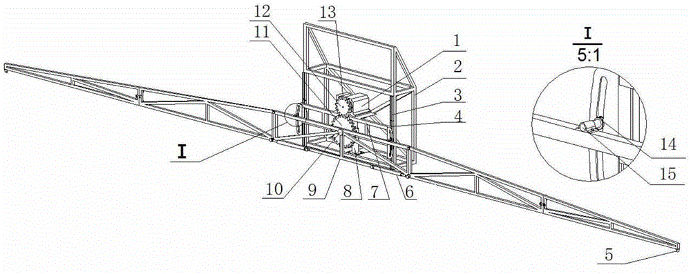
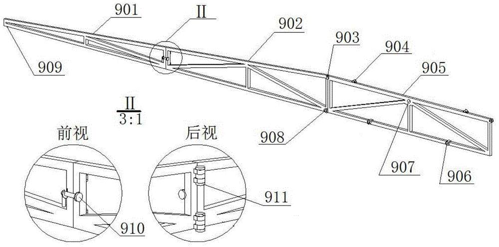
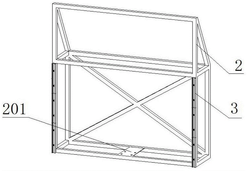
[0029] Such as figure 1 As shown, the automatic adjustment device for spray rod balance according to the present invention includes a DC stepping motor 1, a fixed frame 2, a sliding rail 3, a sliding block 4, a folding hydraulic cylinder 6, a height adjustment frame 7, and a height adjustment hydraulic cylinder 8. , Boom assembly 9, rotating shaft 10, big gear 11, pinion 12, guide pulley 14, guide pulley shaft 15.

[0030] The structure of the height adjustment frame 7 is as Figure 4 As shown, it includes a main body 702, a mounting platform 701 located on the upper part of the main body 702, a guide plate 703 located on both sides of the main body 702, and a rotating shaft seat hole 705 located at the bottom of the main body 702 and perpendicular to it. The guide plate 703 is opened There ...


PUM


Abstract

The invention provides an automatic regulating device for spray lance balance. The automatic regulating device comprises a DC step motor, a fixing frame, a slide rail, a slider, a folding hydraulic cylinder, a height regulating rack, a height regulating hydraulic cylinder, a spray lance unit, a rotary shaft, a large gear, a small gear, a guide pulley, a guide pulley shaft, a distance measurer and a controller. When a sprayer operates, the distance measurer measures signals of distances from two ends of the spray lance to the crop canopy; the signals are sent to the controller; the controller controls the DC step motor to drive the spray lance so as to regulate the balance of the spray lance. The automatic regulating device allows vertical plane motion of the spray lance to be effectively controlled and horizontal plane motion of the spray lance to be effectively reduced; the automatic regulating device is suitable for slope operations and helps improve spray deposition uniformity.

Description

Technical field [0001] The invention relates to the field of agricultural plant protection machinery, in particular to a spray rod balance automatic adjustment device. Background technique [0002] As an engineering equipment for chemical control of agricultural diseases, insects and weeds, boom sprayers have the characteristics of high operating efficiency and easy automation. They have been widely used in countries with high levels of agricultural mechanization in Europe and the United States. my country is also focusing on supporting the development of high-efficiency boom sprayers in the "Eleventh Five-Year" 863 plan. When the boom sprayer is in operation, external excitation (such as uneven ground, acceleration of the sprayer chassis, etc.) can easily deviate the spray rod from the normal motion posture, cause the spray rod to move out of balance, and cause the spray rod to produce horizontal and vertical movements. In 1998, L.Clijmans pointed out through a study that the h...

Claims


Application Information

Patent Timeline
Patent Type & Authority Applications(China)
IPC IPC(8): A01M7/00
Inventor 邱白晶周海涯
Owner JIANGSU UNIV
Learn More