A Series Shock Absorber Based on Leaf Springs

A technology of leaf springs and shock absorbers, which is applied in the field of tandem shock absorbers, can solve the problems of large size of the shock absorber system, small radial bearing capacity, and large height space, etc., and achieves expanded application range, easy assembly, and simplified design Effect

Active Publication Date: 2017-04-05
BEIJING INST OF RADIO MEASUREMENT
View PDF8 Cites 0 Cited by
  • Summary
  • Abstract
  • Description
  • Claims
  • Application Information

AI Technical Summary

Problems solved by technology

Traditionally, shock absorbers are often connected in series to improve the vibration reduction effect by means of multi-stage vibration reduction. However, this series connection method makes the size of the shock absorption system in the height direction larger, which limits its scope of application and cannot be used for height requirements. Harsh use environment, such as shock absorption of sensitive electronic components
[0004] Due to the large size of the traditional series method, there are usually only two stages of vibration damping, and the adjustable range of the total stiffness of the vibration damping system is very small, which brings difficulties to the vibration damping design
When traditional shock absorbers are connected in series, the intermediate adapter plate needs to be designed separately. Although the application of intermediate mass improves the high-frequency vibration reduction effect, it also greatly increases the design complexity.
After searching, it is found that the patent application 200510128866.1 describes a typical shock absorber based on a steel wire rope, which is mainly composed of a first fixed seat, a second fixed seat, and a multi-layer steel wire rope, and the three are screwed together; this design overcomes the helical spring The shock absorber has the disadvantages of small damping and small radial load-bearing capacity, but because the elastic element is a steel wire rope with a large size, the height space occupied by the installation is large, and the height of the two-stage vibration reduction based on its design is larger

Method used


Image

  • A Series Shock Absorber Based on Leaf Springs
  • A Series Shock Absorber Based on Leaf Springs
  • A Series Shock Absorber Based on Leaf Springs

Examples


Embodiment Construction

[0029] The principles and features of the present invention are described below in conjunction with the accompanying drawings, and the examples given are only used to explain the present invention, and are not intended to limit the scope of the present invention.

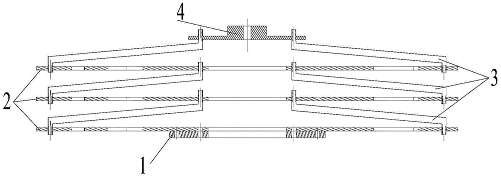
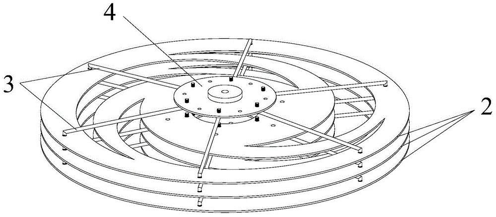
[0030] like figure 1 , 2 As shown, a tandem shock absorber based on leaf springs includes a bottom mounting part 1, a plurality of leaf springs 2, a plurality of elastic rods 3 and a top mounting part 4; a leaf spring 2 is fixed on the bottom mounting part 1, Each leaf spring 2 is stacked, and every two leaf springs 2 are supported by a plurality of elastic rods 3 , and the topmost leaf spring 2 is supported and connected to the top mounting part 4 by a plurality of elastic rods 3 .

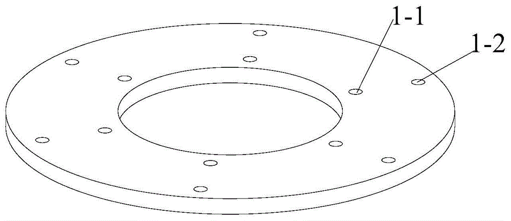
[0031] like image 3 As shown, the bottom mounting part 1 is a sheet-shaped ring structure, the difference between the inner diameter of the sheet-like ring structure and the outer diameter of the ring is a predetermined value, and a...


PUM


Abstract

The invention relates to a flat spring based series damper. The flat spring based series damper comprises a bottom mounting part (1), a plurality of flat springs (2), a plurality of elastic rods (3) and a top mounting part (4), wherein one flat spring (2) is fixed on the bottom mounting part (1); the flat springs (2) are overlapped; every two flat springs (2) are supported through the plurality of elastic rods (3); the flat spring (2) on the top end is connected with the top connecting part (4) under the supporting of the plurality of elastic rods (3). According to the flat spring based series damper, the flat springs are designed, so that the height of a multi-stage series damping system can be greatly reduced, and the applicable scope of the damper can be expanded; the flat springs are connected through the elastic rods, and therefore, the structure of the damper is simple, and the assembling is easy; in addition, the scale of the flat springs can be changed (the quantity of the flat springs and the elastic rods can be increased or decreased), in order to adjust the rigidity of the damper, and as a result, the design is simplified.

Description

technical field [0001] The present invention relates to shock absorbers, in particular to a serial shock absorber based on leaf springs. Background technique [0002] In vibration engineering, as an isolation and absorption device for vibration energy, shock absorbers are widely used in resisting vibration shocks and protecting equipment structures. [0003] Ideally, the lower the stiffness of the shock absorber, the lower the natural frequency and the better the shock absorption effect. Traditionally, shock absorbers are often connected in series to improve the vibration reduction effect by means of multi-stage vibration reduction. However, this series connection method makes the size of the shock absorption system in the height direction larger, which limits its scope of application and cannot be used for height requirements. Harsh use environment, such as shock absorption of sensitive electronic components. [0004] Due to the large size of the traditional series method...

Claims


Application Information

Patent Timeline
Patent Type & Authority Patents(China)
IPC IPC(8): F16F7/104F16F7/116
CPCF16F1/185F16F1/26F16F7/00
Inventor 翁俊严洲徐望王庆
Owner BEIJING INST OF RADIO MEASUREMENT
Why Eureka
Try Eureka